Buyer situation
A magnetic or electromechanical assembly is moving from prototype fit checks toward pilot release.
A structured proof path for locking magnet grade, orientation, carrier geometry, bonding assumptions, runout, balance, and pilot-release evidence before repeat builds.
Proof boundary: Defines the evidence buyers should request and lock during RFQ, pilot, and release gates.
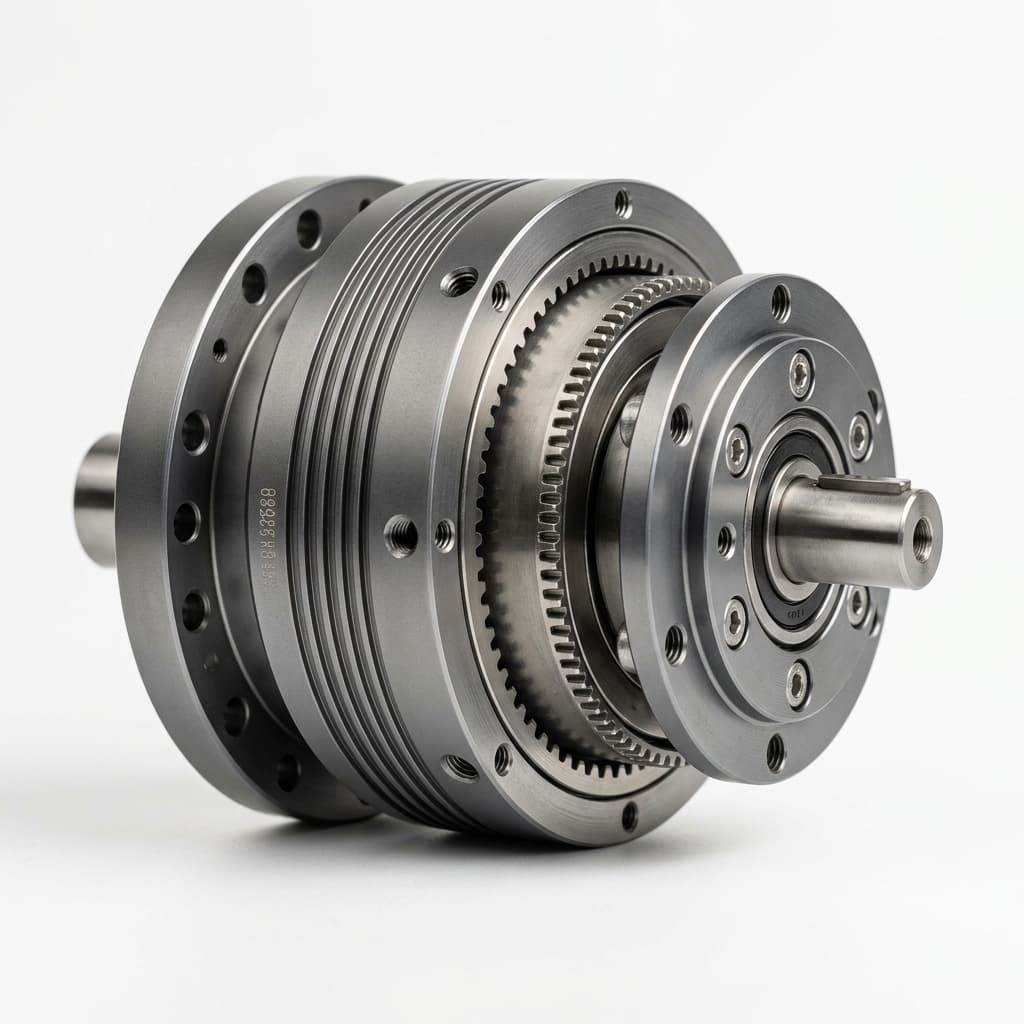
Representative motion-hardware visuals frame magnet bonding, carrier fit, runout/balance, and pilot document-pack discussions; they should not be read as a named customer magnetic assembly photo.
A magnetic or electromechanical assembly is moving from prototype fit checks toward pilot release.
Engineering-reviewed partner execution with Linkup-governed intake, CTQ lock, document-pack planning, and release gates.
This is a template-guided public proof path, not a completed customer case.
Magnet grade, coating, orientation, adhesive, carrier fit, runout, balance, and release documents often arrive as disconnected assumptions.
Magnetic assemblies, magnet carriers, rotor/stator-adjacent hardware
Magnetic assembly prototype-to-pilot
Magnetic assembly / pilot validation
| Feature | Why it matters | Evidence path |
|---|---|---|
| Magnet grade, coating, and orientation | The RFQ needs grade assumptions, coating constraints, magnetization direction, polarity/orientation controls, and handling notes. | RFQ lock checklist plus drawing or specification references for orientation and coating assumptions. |
| Carrier fit and bonding window | Pocket fit, adhesive gap, cure assumptions, surface preparation, and retention risk need a shared process window. | Bonding process window, fixture notes, and pilot-gate acceptance checklist. |
| Runout, balance, and assembly evidence | Air-gap-adjacent features should connect geometry, assembly handling, and inspection expectations before pilot freeze. | Representative runout/balance checks, visual inspection, and document-pack release summary. |
Risk: Pilot builds can drift if grade, coating, orientation, fit, and adhesive assumptions change separately.
Control: Use one intake checklist to lock magnetic, mechanical, and evidence assumptions before route selection.
Risk: Late adhesive or coating changes can alter fit, retention, and verification work.
Control: Document adhesive gap, surface state, fixture approach, cure assumptions, and inspection expectations.
Risk: A visually acceptable assembly may still miss runout, balance, or document-pack expectations.
Control: Freeze acceptance gates before pre-ship release.
Collect magnet grade, orientation, coating, carrier datum, bonding, runout, balance, and document-pack needs up front.
Translate prototype lessons into pilot verification requirements before repeat-build handoff.
Separate Linkup-governed engineering review and release coordination from upstream magnet manufacturing ownership claims.
Aligns magnet, carrier, bonding, inspection, and documentation requirements.
Captures fit, adhesive, surface, cure, and inspection assumptions.
Defines what must be available before repeat-build handoff.
The public page should not imply owned magnet production, owned motor production, or complete robot module manufacturing.
Linkup can govern magnetic assembly intake, CNC carrier interfaces, partner-routed process coordination, and evidence planning.
Buyer-owned performance validation remains separate from manufacturability and inspection evidence unless explicitly supplied.
This proof page maps a scoped manufacturing route, not full system ownership. Linkup governs DFM review, CTQ translation, partner-route coordination, inspection expectations, and release documentation while customer-owned architecture and acceptance validation remain separate.
Commercial intake, engineering review, route planning, quality expectations, progress follow-up, and release coordination stay under Linkup governance.
Qualified manufacturing partners execute approved machining, finishing, assembly, inspection, balancing, packaging, or shipment tasks by program scope.
Final product architecture, system-level validation, proprietary design intent, acceptance thresholds, and certification decisions remain customer-owned.
The magnetic-to-motion thread is a manufacturing-scope map, not a claim of self-owned raw-material-to-robot production.
These selected visuals point to the actual interface, inspection, or document-pack concept behind the proof path. They are not decorative factory imagery.
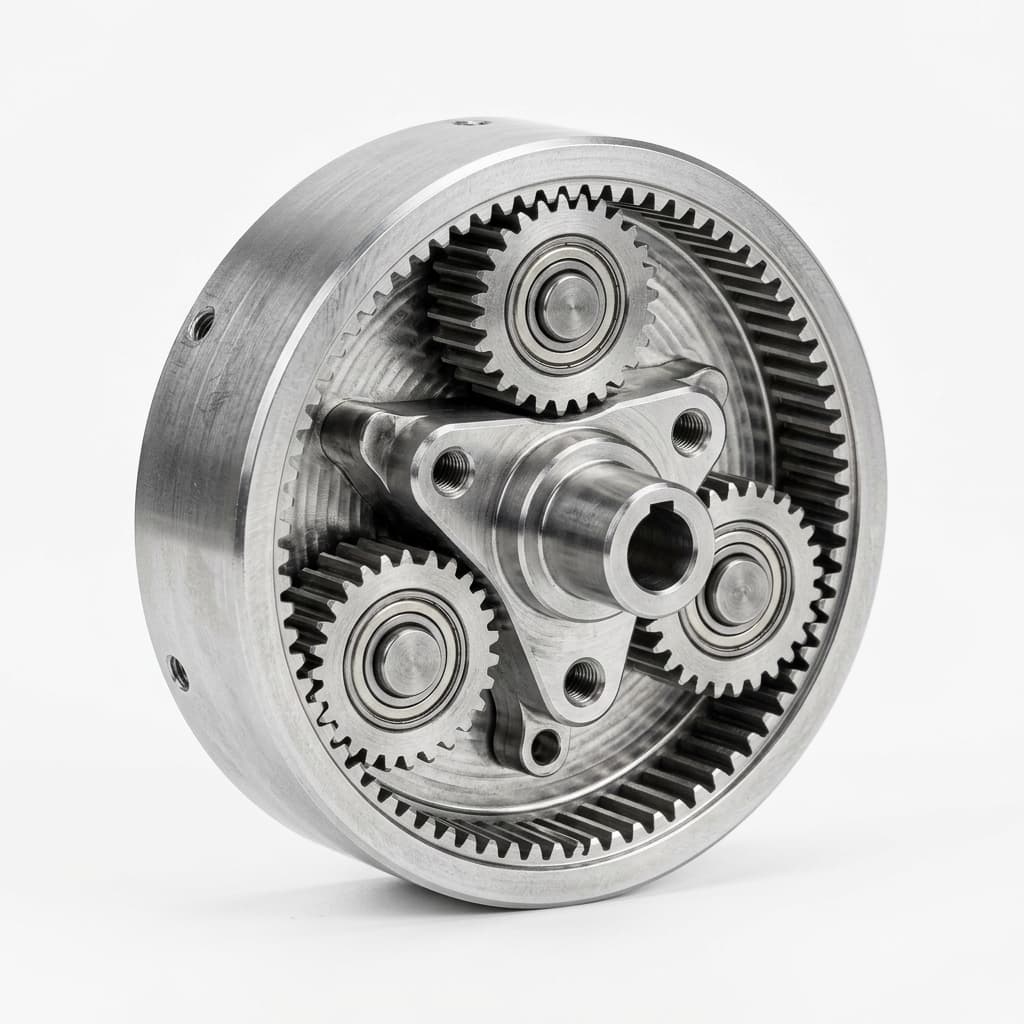
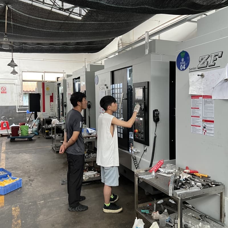
Upload CAD and drawings for a one-business-day first response when the RFQ package is complete. We review magnetic assembly, actuator-adjacent, complex CNC interface, and prototype-to-pilot risks before quote direction and partner-route planning.
Typical 5-9 working day CNC sample timing applies only when the CNC route is qualified after scope, material, inspection, partner route, and schedule review. Assembly and pilot support are scoped separately after prototype assumptions are clear.
Inquiry Email
For NDA-sensitive drawings, include your revision ID and target timeline in the first email.