Buyer situation
Prototype actuator hardware with multiple related part numbers and drawing-driven inspection expectations.
An anonymized robotics actuator proof path showing how drawing interpretation, fit-risk mapping, and inspection planning support fast CNC sample execution.
Proof boundary: Built from a real proof pattern with customer identity, proprietary drawings, and sensitive dimensions removed.
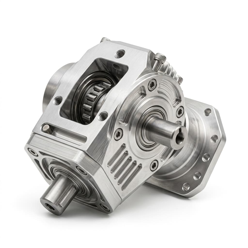
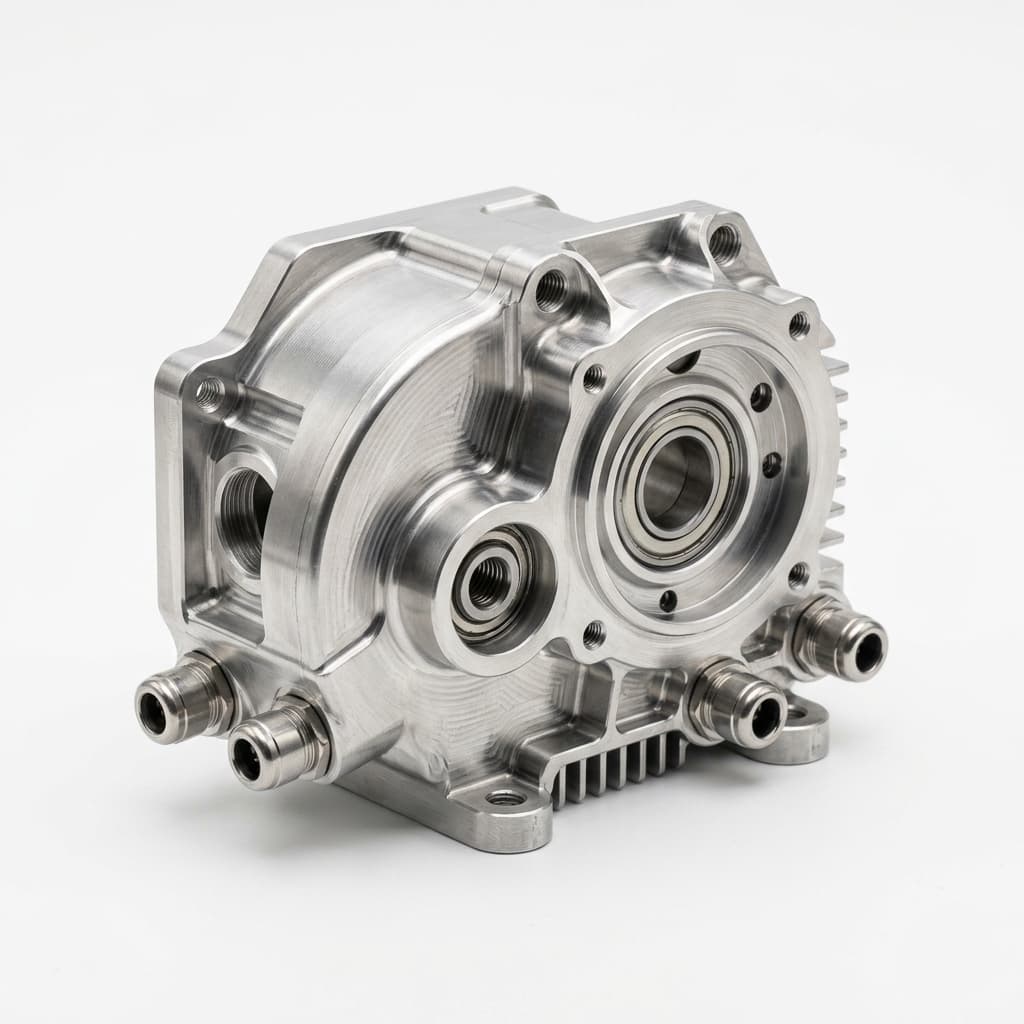
Representative actuator visuals are selected to anchor the proof around bearing seats, flange datums, motor-mount faces, and release inspection evidence, not around confidential customer drawings.
Prototype actuator hardware with multiple related part numbers and drawing-driven inspection expectations.
Engineer-reviewed CNC sample route with CTQ extraction before shop-floor release.
Customer identity, dimensions, and drawings stay confidential; the public case only shows sanitized workflow themes.
A robotics actuator sample package needed rapid CNC execution without losing bearing, motor-mount, fine-thread, and load-path intent from the drawing set.
Robotics actuator housings, rotor supports, and motor-mount CNC parts
Robotics actuator prototype
Motor-adjacent CNC / robotics actuator
| Feature | Why it matters | Evidence path |
|---|---|---|
| Bearing and shaft fits | Fit-class callouts, coaxial bore relationships, and mating shaft assumptions needed to stay visible during quoting and machining. | CTQ list tied to drawing references, CMM or gauge method, and release notes. |
| Motor-mount and reducer datums | Mounting faces, dowel holes, flange flatness, and datum chains controlled assembly behavior more than outer shape. | Datum strategy review and inspection plan before first sample release. |
| Fine threads and similar variants | Small thread pitch, blind-hole depth, and similar-looking part variants created mix-up and tool-risk exposure. | Factory notes for thread risk, part identification, and revision-controlled release. |
Risk: A fast upload-style quote could miss which features controlled actuator function.
Control: Separate cosmetic geometry from CTQ features before releasing the CNC route.
Risk: Variants could be treated as interchangeable if the release notes were too generic.
Control: Add variant-specific warnings and part descriptions to manufacturing instructions.
Risk: Critical bores, datums, or threads might be difficult to verify after setup decisions.
Control: Tie CTQs to inspection method and acceptance evidence before sample production.
Engineering review extracted fit classes, datum relationships, thread risks, and assembly-interface notes before quote lock.
The manufacturing path carried explicit feature priorities into machining and inspection planning.
The public case avoids customer names, original dimensions, and proprietary screenshots.
Shows which bearing, datum, thread, and interface features drove review.
Captures manufacturability risks before quote and route release.
Connects release expectations to CMM, gauge, or drawing-based checks.
Linkup supports component manufacturing and engineering review for actuator hardware; the public proof does not claim complete actuator module ownership.
Performance outcomes are not published without buyer-side test evidence and permission.
The proof is useful for RFQs where CAD speed must be balanced with fit, datum, and inspection risk.
This proof page maps a scoped manufacturing route, not full system ownership. Linkup governs DFM review, CTQ translation, partner-route coordination, inspection expectations, and release documentation while customer-owned architecture and acceptance validation remain separate.
Commercial intake, engineering review, route planning, quality expectations, progress follow-up, and release coordination stay under Linkup governance.
Qualified manufacturing partners execute approved machining, finishing, assembly, inspection, balancing, packaging, or shipment tasks by program scope.
Final product architecture, system-level validation, proprietary design intent, acceptance thresholds, and certification decisions remain customer-owned.
The magnetic-to-motion thread is a manufacturing-scope map, not a claim of self-owned raw-material-to-robot production.
These selected visuals point to the actual interface, inspection, or document-pack concept behind the proof path. They are not decorative factory imagery.
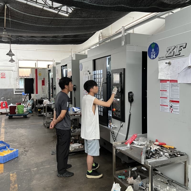
Upload CAD and drawings for a one-business-day first response when the RFQ package is complete. We review magnetic assembly, actuator-adjacent, complex CNC interface, and prototype-to-pilot risks before quote direction and partner-route planning.
Typical 5-9 working day CNC sample timing applies only when the CNC route is qualified after scope, material, inspection, partner route, and schedule review. Assembly and pilot support are scoped separately after prototype assumptions are clear.
Inquiry Email
For NDA-sensitive drawings, include your revision ID and target timeline in the first email.