Buyer situation
A motor-adjacent carrier or housing needs CNC samples that preserve fit and inspection intent.
A recreated demonstration for motor-adjacent carriers and housings where CNC geometry, bearing seats, encoder datums, and assembly interfaces must be reviewed together.
Proof boundary: Shows a representative DFM and inspection workflow based on recurring part-family risks, not a named customer result.
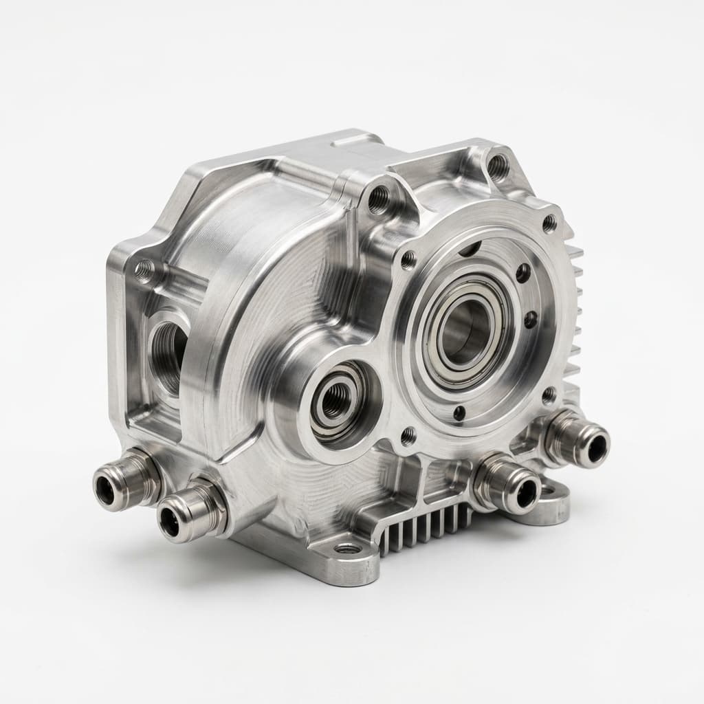
Representative carrier and housing visuals are selected for bearing-seat, encoder-datum, flange-flatness, finish, and inspection-plan discussion.
A motor-adjacent carrier or housing needs CNC samples that preserve fit and inspection intent.
Prototype CNC route with DFM review for bearing fits, encoder datums, flange flatness, runout, and finish effects.
This is a recreated public workflow built from recurring part-family risks, not a customer performance result.
Carrier and housing parts can look like ordinary CNC work while carrying air-gap-adjacent, bearing, shaft, encoder, and flange risks.
Motor-adjacent carriers, housings, flanges, and sensor mounts
Motor-adjacent CNC prototype
Motor-adjacent CNC / carrier housing
| Feature | Why it matters | Evidence path |
|---|---|---|
| Bearing seats and shaft interfaces | Bore size, roundness, coaxiality, perpendicularity, and finish can decide whether the assembly is usable. | CTQ inspection map with gauge or CMM method tied to the buyer drawing. |
| Encoder and sensor datums | Sensor mounts, cable exits, datum faces, and fastener patterns need review against assembly stack-up. | Datum review notes and inspection plan for sensor-mount geometry. |
| Flange flatness and runout | Interface faces, dowel holes, and bolt patterns can control mating behavior after finish and assembly. | Flatness, runout, and hole-position evidence defined before sample release. |
Risk: Treating the order as generic CNC can miss why a bore, flange, or datum face matters.
Control: Classify the RFQ as motor-adjacent CNC and map CTQs before quoting.
Risk: Coating or anodize assumptions may affect fits, grounding, or assembly clearance.
Control: Define finish-sensitive features and masking assumptions during DFM.
Risk: A sample can be machined correctly but still fail buyer release if evidence is incomplete.
Control: Select inspection artifacts before sample route release.
RFQs are flagged for bearing, shaft, sensor, and air-gap-adjacent features rather than handled as anonymous CNC parts.
Manufacturability notes and evidence expectations are reviewed together to reduce late-release surprises.
Accepted sample assumptions become the baseline for pilot build review.
Captures bearing, shaft, flange, encoder, and finish-sensitive features.
Shows how routing decisions change before quote lock.
Defines CMM, gauge, runout, flatness, or document-pack needs.
This proof supports component-level CNC and inspection review; it does not claim motor design or motor performance validation.
Assembly-fit recommendations depend on buyer drawings, mating components, and acceptance requirements.
Prototype-to-pilot guidance should stay tied to documented sample evidence.
This proof page maps a scoped manufacturing route, not full system ownership. Linkup governs DFM review, CTQ translation, partner-route coordination, inspection expectations, and release documentation while customer-owned architecture and acceptance validation remain separate.
Commercial intake, engineering review, route planning, quality expectations, progress follow-up, and release coordination stay under Linkup governance.
Qualified manufacturing partners execute approved machining, finishing, assembly, inspection, balancing, packaging, or shipment tasks by program scope.
Final product architecture, system-level validation, proprietary design intent, acceptance thresholds, and certification decisions remain customer-owned.
The magnetic-to-motion thread is a manufacturing-scope map, not a claim of self-owned raw-material-to-robot production.
These selected visuals point to the actual interface, inspection, or document-pack concept behind the proof path. They are not decorative factory imagery.
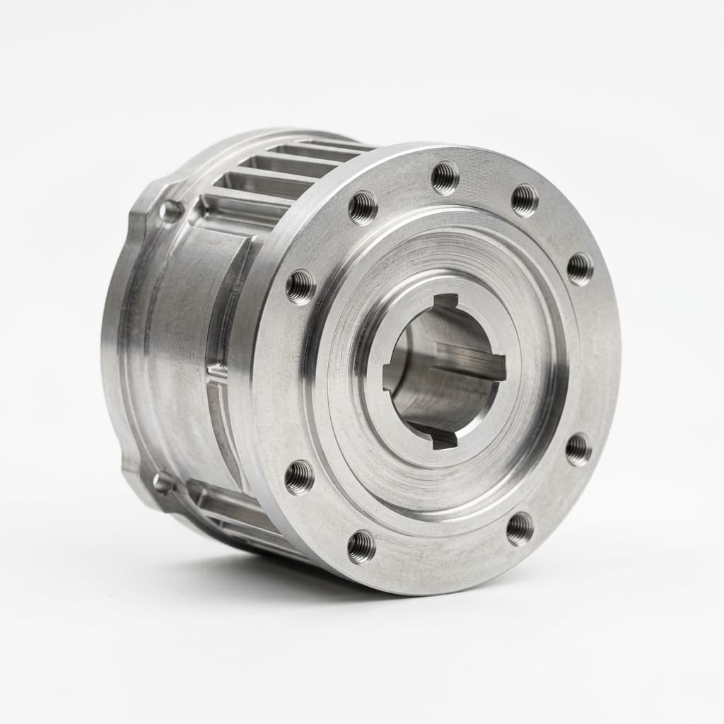
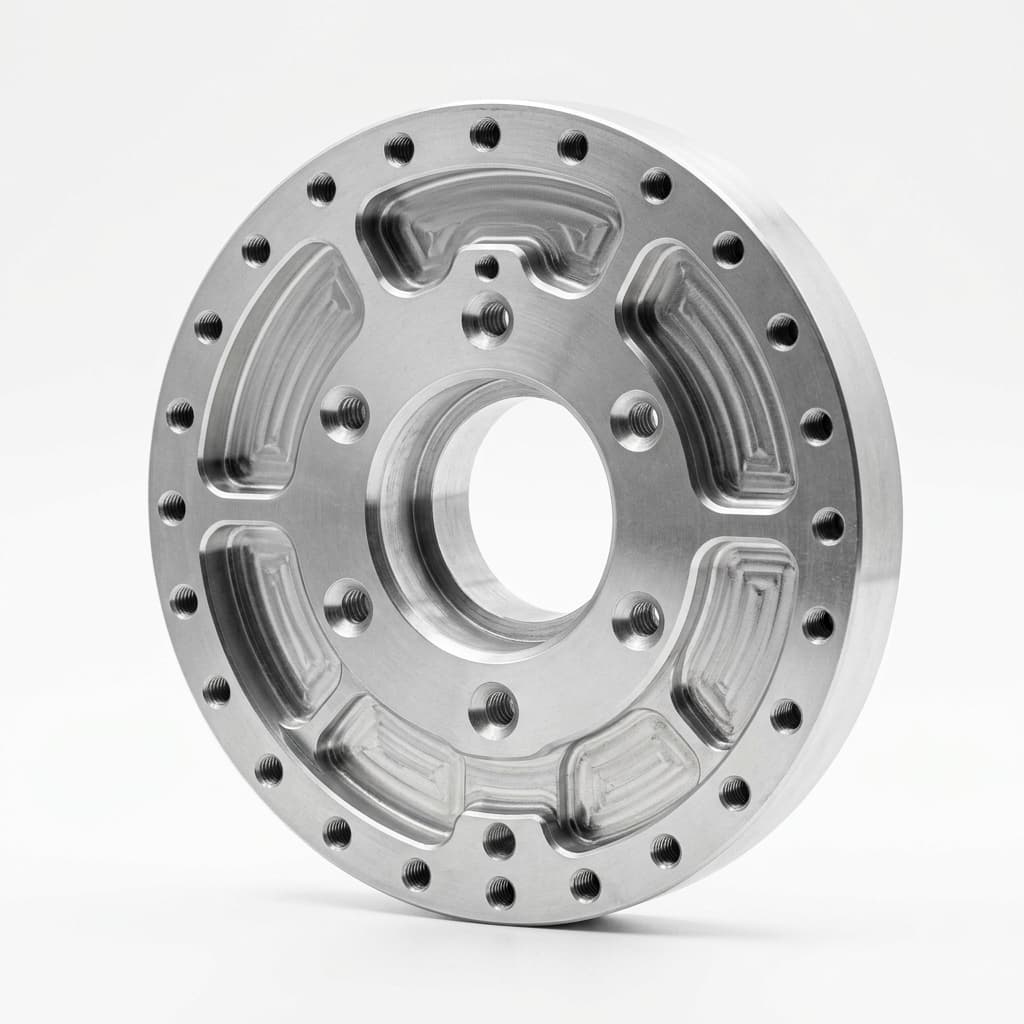
Upload CAD and drawings for a one-business-day first response when the RFQ package is complete. We review magnetic assembly, actuator-adjacent, complex CNC interface, and prototype-to-pilot risks before quote direction and partner-route planning.
Typical 5-9 working day CNC sample timing applies only when the CNC route is qualified after scope, material, inspection, partner route, and schedule review. Assembly and pilot support are scoped separately after prototype assumptions are clear.
Inquiry Email
For NDA-sensitive drawings, include your revision ID and target timeline in the first email.