Precision Optical & Rotary Encoder Housing CNC Machining: A Buyer’s DFM Guide
Source precision optical and rotary encoder housings with a buyer’s DFM guide to runout, air-gap budgets, material trade-offs, and inspection. Prepare your RFQ.
Published and last reviewed: 05 November 2026. Topic: Precision Machining. Region: Global. Audience: robotics electromechanical engineers, joint actuator NPI managers, optical gimbal designers, and motion control procurement specialists.
Precision optical and rotary encoder housing CNC machining connects sensor specifications to assembled motion accuracy. In robotics, tracking gimbals, and semiconductor handling stages, a high-resolution encoder can still show periodic position error if its scale, bearing axis, and readhead are misaligned. Specify the exact encoder model and compatible scale rather than treating incremental optical kits, absolute optical kits, and inductive or capacitive encoders as interchangeable.
The machined mechanical housing, bearing seats, and rotor hub adapters are part of that error budget. Sensor scale accuracy, interpolation, electronics, bearing behavior, and assembly alignment also matter; a housing inspection alone cannot establish complete encoder accuracy.
When a modular encoder disc or magnetic ring is unhoused, the host machine structure becomes the metrological frame. As the worked example below shows, 15 µm radial Total Indicated Runout (TIR) on an ideal 60 mm pitch-diameter scale corresponds to approximately 51.6 arcseconds of peak eccentricity error. Axial end-play and mounting face tilt can also move the readhead outside its model-specific installation envelope, degrading the signal or risking contact.
This guide provides an engineering and procurement framework for sourcing precision optical and rotary encoder housings. Use this resource alongside our encoder housing and sensor mount machining scope, our motion hardware integration overview, and our precision CNC machining scope. To initiate a DFM and tolerancing review, submit your drawings and encoder installation envelope.
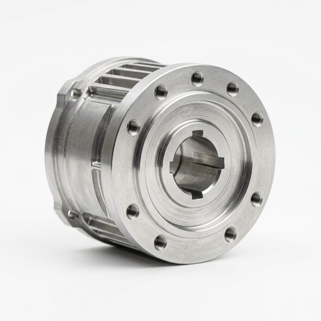
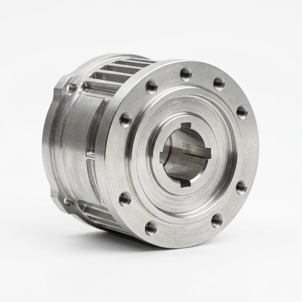
Illustrative hardware only. This image depicts representative CNC machined encoder housing geometry; exact material temper, surface finish, anodize thickness, and GD&T runout tolerances are defined by the released customer drawing.
Scope and Engineering Boundaries
This DFM guide covers CNC turning, 5-axis mill-turn machining, datum sequencing, and metrology for custom housings and adapters supporting unhoused rotary encoder kits (optical and magnetic).
- Applicable assemblies: Bearingless modular optical encoders, magnetic scale rings, dual-readhead robotic joint housings, hollow-shaft motor end-bells, and gimbal azimuth/elevation encoder brackets.
- Cooling and environmental boundaries: Evaluate the actual assembly temperature range, gradients, humidity, and contamination exposure. A range such as -40°C to +85°C is a design input to confirm, not a rating established by this guide. Cryogenic or ultra-high-vacuum applications require separate qualification.
- Customer design authority: Sensor kit selection, optical scale line count, electronic interpolation parameters, bearing arrangement, joint preload, and system dynamic bandwidth.
- Supplier manufacturing responsibility: Propose machining sequencing, workholding, dimensional allowances, and inspection reporting for agreement with the customer. Any stress-relief heat treatment must preserve the specified material temper and receive design approval.
Evidence boundary: This is a DFM decision framework with reproducible geometric examples, not a measured production case study. The ISO fit-system reference explains fit terminology; the ISO geometrical-tolerancing reference and ASME drawing-standard reference establish their respective drawing languages. Select one governing convention and edition on the drawing. Numerical targets here are illustrative allocations, not standard-mandated limits, encoder OEM specifications, or verified supplier capabilities. Obtain the installation manual for the exact encoder and scale before release.
1. The Resolution vs. Mechanical Accuracy Fallacy
A frequent error in electromechanical procurement is equating encoder resolution with system accuracy:
Resolution ≠ Accuracy
A 20-bit encoder provides 1,048,576 counts per revolution (2^20), yielding a theoretical angular quantization step of:
δθ = 360° / 1,048,576 ≈ 0.000343° ≈ 1.24 arcseconds
However, if the CNC-machined shaft adapter or housing bore introduces a radial eccentricity (e) between the scale center and the axis of shaft rotation, a fundamental once-per-revolution sinusoidal position error is generated:
θ_error(φ) ≈ (e / r) · sin(φ) [radians]
Where e is center offset and r is the optical scale pitch radius. For an ideal circular scale with pure eccentricity, TIR = 2e. Measured runout can also include roundness, bearing motion, fixture error, and tilt, so that conversion requires those effects to be separated.
Worked Example: The Impact of 15 µm Radial Runout
Consider a typical robotics joint encoder with a scale radius r = 30 mm (60 mm diameter):
- Assumed radial TIR:
0.015 mm(15 µm) - Corresponding eccentricity for this idealized example:
e = 0.0075 mm(7.5 µm) - Maximum angular error:
θ_peak = 0.0075 / 30 = 0.00025 radians ≈ 51.57 arcseconds ≈ 0.0143°
The peak error is about 42 quantization steps at 20-bit resolution; peak-to-peak error is approximately 103.13 arcseconds. A 15 µm center offset, by contrast, would mean 30 µm ideal TIR and approximately 103.13 arcseconds peak error. Neither calculation establishes effective accuracy in bits, which requires a defined system error metric and measurements.
Ordinary smoothing does not correct a repeatable angle-dependent bias. Better centering, compatible dual-readhead processing, or validated angle-error calibration may reduce it. Compare their manufacturing, electronics, and calibration costs against the required accuracy rather than assuming the tightest machining tolerance is always economical.
2. Geometric Error Breakdown: Air-Gap, Swashplate Wobble, and Abbe Error
The housing must govern scale centering, readhead clearance, and alignment to the functional bearing axis. Optical pitch, signal processing, and permitted misalignment differ by encoder model. The following sketch identifies interfaces; it does not prescribe a complete datum reference frame.
       +-------------------------------------------------------+
       |             ROBOTIC JOINT HOUSING BODY                |
       |  A: Mounting shoulder; B: bearing-seat axis           |
       +---------------------------+---------------------------+
                                   |
                  +----------------+----------------+
                  |                                 |
         +--------v--------+               +--------v--------+
         | Datum B:        |               | Controlled:     |
         | Bearing Seat    |  Coaxiality   | Encoder Pilot   |
         | Bore            |<=============>| Pilot spigot    |
         | Fit per drawing | Runout to B    | Fit per drawing |
         +--------+--------+               +--------+--------+
                  |                                 |
                  v                                 v
         Bearing Journal Axis              Encoder Scale Axis
                  \                               /
                   \==== Radial Eccentricity ====/
                    C: separate clocking feature if needed
1. Air Gap (Ride Height) Window
Obtain nominal ride height and allowable variation from the exact readhead/scale installation manual. There is no universal optical air-gap window. Outside the permitted envelope, signal quality may deteriorate; the particular warning, interpolation error, or dropout behavior depends on the encoder.
For a hypothetical design allowance of ±50 µm, allocate worst-case deviations from the installed nominal: bearing motion 15 µm + mounting-face contribution 8 µm + scale mounting contribution 5 µm + thermal/load movement 7 µm = 35 µm, leaving 15 µm margin on each side. These are assumed budget inputs, not OEM data. Check both clearance extremes, adjusting the nominal if the stack is asymmetric. Statistical combination needs justified distributions and assembly data; it cannot replace a clearance check where contact would damage the scale.
2. Axial End-Play and Swashplate Wobble (Face Runout)
When an encoder mounting flange is out-of-square with the shaft axis of rotation, the rotating disc experiences swashplate tilt (angular wobble, φ).
- As the shaft rotates, the distance between the readhead and the disc fluctuates once per revolution.
- This dynamic ride-height oscillation creates cyclic modulation of the optical signal amplitude.
- Whether axial float creates angular error depends on the scale geometry and readhead response; verify the OEM's axial and tilt limits separately.
3. Abbe Error in Actuator Encoders
Abbe error occurs when the measuring system is offset from the functional line of action. In hollow-shaft robot actuators, the encoder is commonly positioned at the rear of the motor housing, separated by an Abbe offset distance (d) from the primary joint output bearing:
Δx = d · tan(φ) ≈ d · φ
If the housing structure lacks mechanical rigidity, joint reaction moments cause the motor casing to flex by angle φ. Over an offset distance d = 120 mm, an angular elastic deflection of just 0.02° translates to:
Δx = 120 mm · tan(0.02°) ≈ 41.9 µm
This is a linear offset calculation, not a direct rotary encoder angular-error prediction. Use it to examine load paths and sensor separation; translating it into joint angle requires the actual mechanism geometry, stiffness, and encoder location.
3. Structural Tolerance and Failure-Mode Matrix
The following matrix maps housing interfaces to failure modes and candidate controls. Values are example drawing allocations for quotation discussion; approve each against the sensor, bearing, part geometry, and inspection uncertainty.
| Mechanical Feature | Target GD&T Callout | Standard Fit Class | Associated Failure Mode | Preventative CNC Machining Control |
|---|---|---|---|---|
| Bearing seat bore | Example cylindricity ≤ 0.003 mm | Fit selected for bearing and load | Excess clearance or ring distortion | Precision boring or grinding; inspect unclamped form |
| Encoder mounting spigot | Example radial circular runout ≤ 0.005 mm to B | Fit selected for scale pilot | Once-per-rev eccentricity error | Finish pilot and bearing bore in common workholding if accessible |
| Readhead mounting pads | Example parallelism ≤ 0.005 mm to A | Example Ra ≤ 0.8 µm | Uneven ride height or readhead tilt | Finish pads after stabilization; inspect assembled alignment |
| Sensor bracket alignment holes | Example position zone diameter 0.010 mm to agreed datums | Dowel fit and thread per drawing | Assembly adjustment range exhausted | Jig boring or reaming with position verification |
| Housing mating flange | Example axial circular runout ≤ 0.005 mm to B | Face A; orientation per drawing | Scale face wobble and clearance variation | Face turning; inspect relative to functional axis |
| Rotor hub adapter seat | Example radial circular runout ≤ 0.003 mm to its bearing axis | Fit selected for rotating assembly | Scale offset or dynamic unbalance | Qualified mandrel or common setup; balance if application requires |
| Internal cable transit bores | Burr-free edge break per cable design | Visual or borescope inspection | Insulation chafing and signal interruption | Deburr accessible edges; check cable bend radius and strain relief |
4. Visual: Datum Hierarchy and Single-Setup Tolerancing Architecture
The diagram below separates the mounting face, bearing axis, pilot, and readhead interfaces. In this example, A is the mounting face, B is the bearing-seat axis, and an optional C feature clocks the part. A second coaxial pilot does not supply an independent clocking datum. Confirm datum precedence and controlled features from the assembly function.
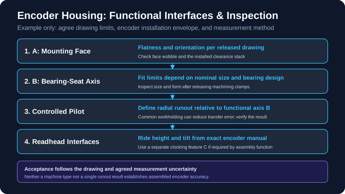
Illustrative datum architecture only. Dimensional limits, GD&T callouts, and inspection protocols are defined by the customer's released engineering drawing.
5. Material Selection and CTE Mismatch Dynamics
A critical factor frequently overlooked during procurement is the Coefficient of Thermal Expansion (CTE) mismatch between the housing, the optical scale, and the host motor shaft.
Use supplier-certified expansion data for the selected housing alloy, scale substrate, adhesive, and operating interval. Glass grades and steel alloys differ; the word “glass” or “stainless” does not determine the coefficient. The relevant clearance direction also depends on whether the readhead reads a disc face or a cylindrical ring.
For a screening example, assume housing CTE 23 × 10^-6/K, scale CTE 9 × 10^-6/K, nominal mating diameter 60 mm, and uniform temperature rise 50 K. Differential free expansion is ΔD = (23 - 9) × 10^-6 × 60 × 50 = 0.042 mm across the diameter, or 21 µm per side. This estimates radial fit change; it does not predict an axial optical gap or adhesive stress. A bonded or constrained assembly needs a separate mechanical model.
Material Selection Matrix for Precision Encoder Housings
| Material Candidate | Reason to Consider | DFM Limitation | Evidence to Request |
|---|---|---|---|
| 6061 stress-relieved stock | Lightweight general-purpose housings | Thin-wall movement and thermal fit change | Product form, temper certificate, and unclamped dimensions |
| 7075 stress-relieved stock | Higher-strength compact structures | Strength does not imply a proportional stiffness increase | Load calculation, corrosion requirements, and stock certification |
| AISI 416 stainless | Machinable steel interface candidate | Magnetic behavior and corrosion suitability need review | Magnetic compatibility and environment-specific material approval |
| AISI 303 stainless | Machinability in austenitic stainless parts | Corrosion and magnetic response depend on condition | Grade certificate and acceptance requirements |
| AISI 304 / 316 stainless | Corrosion-driven housing applications | Cold work can affect magnetic response; machining is more demanding | Corrosion selection basis and finished-part magnetic limits if relevant |
| Invar 36 | Low-expansion structures over a qualified interval | High mass, machining cost, and condition-dependent stability | CTE over service temperature and an approved stabilization route |
DFM Advice on Aluminum Housing Anodizing
When sourcing aluminum encoder housings with Type II or Type III (hardcoat) anodizing:
- Specify finished condition: Agree which bearing seats and pilots are masked, dimensionally compensated, or finish-machined after coating. Post-coat machining exposes the substrate and must satisfy corrosion requirements.
- Tolerance impact: Total oxide thickness and outward dimensional growth are different quantities. Obtain the finisher's allowance for the actual pretreatment and coating process. If outward growth is assumed to be 10 µm per surface, a coated bore loses about 20 µm in diameter. H6/h6 tolerance widths depend on nominal size; neither denotes a universal 8 µm window.
- Hole precautions: Define final dowel-hole and thread acceptance after coating. Use suitable plug/thread gauges or calibrated air gauging for size; inspect hole position separately. Reaming corrects size and finish but does not by itself establish positional accuracy.
6. Machining Strategy: Single-Setup Mill-Turn vs. Multi-Setup Lathe
An important manufacturing decision is setup continuity: which critical surfaces can be finished without disturbing their relationship? Common workholding can reduce transfer error, but equipment type alone does not prove a finished tolerance.
Candidate Multi-Setup Route
[Setup 1: Chuck on OD] ----> Unclamp & Flip Part ----> [Setup 2: Re-chuck on OD]
          |                                                       |
          v                                                       v
Turn Bearing Seat Bore                                Turn Encoder Pilot Spigot
          |                                                       |
          +------------------ Runout Error Stack -----------------+
                    (Measure transfer error; no assumed value)

Candidate Common-Setup Route
[Main Spindle: Turn Datum A, B, C simultaneously] ----> Sub-Spindle Synchronous Handoff
                         |                                           |
                         v                                           v
            Single Chucking Operation                  Back-work & Milled Readhead Pads
                         |                                           |
                         +------------ Verified Coaxiality -----------+
                               (Verify drawing acceptance)
Process Comparison: Single-Setup Mill-Turn vs Conventional Multi-Setup
| Evaluation Dimension | Conventional Multi-Setup Lathe | Single-Setup 5-Axis Mill-Turn | Impact on Encoder Functionality |
|---|---|---|---|
| Bearing-to-pilot relationship | Requires qualified locating surfaces and transfer inspection | May finish both in one clamping | Compare measured runout against the same functional datum |
| Flange face orientation | Must recover the bearing-axis reference after transfer | May face and bore without transfer | Check face runout and the resulting clearance stack |
| Clamping distortion | Depends on jaw contact and force | Also depends on jaw contact and force | Inspect released-part form, not only in-chuck size |
| Readhead alignment holes | May use a dedicated accurate fixture | May use live tooling where accessible | Verify position and adjustment travel; no automatic advantage |
| Pilot-batch yield | Request records for the proposed route | Request records for the proposed route | No comparative scrap-rate data are established here |
| Metrology correlation | Requires agreed datum simulation and methods | Requires the same inspection agreement | Accept evidence and uncertainty, not a machine label |
Qualifying a Multi-Setup Route
A supplier may finish the mounting face and bearing bore in Setup 1, then relocate the part to finish the pilot in Setup 2. That route can work if its locating fixture, clamp force, and transfer error are qualified.
- Ask which finished surface locates the second setup and how its cleanliness and wear are controlled.
- Check bore roundness after release; a thin housing can spring back from either route.
- Inspect the final pilot relative to the functional bearing axis, rather than adding unrelated in-process measurements and calling the stack acceptable.
A Common-Setup Route to Discuss at RFQ
Ask Linkup Precision to review the following candidate sequence against the drawing and available qualified manufacturing capacity:
- Roughing and stabilization: Leave appropriate finishing stock and allow the workpiece to reach inspection temperature. A cooling pause is not metallurgical stress relief; any heat treatment needs an approved procedure compatible with the alloy and temper.
- Common finish turning: Where geometry permits, bore the bearing seat, face the shoulder, and turn the pilot in the same clamping. Select tooling for the alloy and required surface integrity. Record the final runout rather than assuming spindle alignment guarantees it.
- Readhead interfaces: Machine pads and locating holes in common workholding or a qualified fixture. Check released-part alignment and whether the sensor can be adjusted across its installation range.
- Reverse-side operations: A sub-spindle transfer, mandrel, or dedicated fixture can provide access. Each transfer needs qualification; synchronized spindle motion does not eliminate locating or clamping error.
If the drawing still says only “precision bore” or “20-bit compatible,” send the bearing interface and encoder installation requirements for DFM review before comparing quotes. A useful quote identifies the accepted drawing revision, finished coating condition, inspection deliverables, and assumptions that remain open.
7. Dual Readhead Integration: Mechanical Design and Housing Coplanarity
Some systems use dual readheads arranged at 180° opposing positions. Confirm that the selected encoder and controller support this architecture, including angle registration, signal combination, timing, and calibration.
The Mathematical Advantage of Dual Readheads
When two readheads (R1 and R2) read the scale diametrically opposite each other, their angular measurements are:
θ1 = θ_true + (e / r) · sin(φ) + ε1
θ2 = θ_true - (e / r) · sin(φ) + ε2
By calculating the arithmetic average:
θ_avg = (θ1 + θ2) / 2 = θ_true + (ε1 + ε2) / 2
The first-order eccentricity term cancels in this ideal model after correcting the heads' angular offset and unwrapping their readings. Residual errors ε1 and ε2 include interpolation, scale, timing, and alignment effects. Averaging does not establish their cancellation, compensate every harmonic, or guarantee a particular accuracy in bits.
Single Readhead vs Dual Readhead Housing Requirements
| Mechanical Constraint | Single Readhead Architecture | Dual Readhead Architecture (180° Opposed) | Sourcing / Machining Implication |
|---|---|---|---|
| Radial eccentricity | First-order term remains without correction | Ideal opposed-head average cancels that term | Allocate residual error and clearance independently |
| Mounting pads | One ride-height and tilt stack | Two independently acceptable stacks | Coplanarity follows the selected kit and mounting scheme |
| Angular separation | Locate one readhead relative to scale | Opposed geometry plus electronic registration | Set hole position from an angular error allocation |
| Cable egress | One signal path | Two paths and associated timing/interface constraints | Preserve cable shielding, bend radius, and service access |
| Housing envelope | One bracket region | Clearance needed around both reading positions | Check flange stiffness and thermal symmetry |
| Total integration cost | One head and simpler processing | Additional head, processing, and validation | Compare total system cost against a measured accuracy requirement |
The Mechanical Housing Burden
Dual readheads add interfaces to control:
- Pad alignment: Both heads must remain within their own ride-height and tilt limits throughout rotation, temperature change, and loading. Shims or adjustable brackets may be acceptable if the OEM permits them; a universal 0.008 mm coplanarity limit is not justified.
- Angular separation: Hole position tolerance and angular separation are different requirements. At a 30 mm mounting radius, an assumed tangential offset of 0.010 mm represents about 0.019° for one head. Specify the positional tolerance zone, mounting radius, assembly adjustment, and registration method rather than claiming a position value guarantees exactly 180°.
8. Sourcing & DFM Acceptance Checklist
Before approving tooling or releasing production purchase orders for precision encoder housings, procurement and engineering teams should review this 10-point checklist:
- 1. Datum Reference Frame Locked: Does the drawing identify the mounting face, functional bearing axis, and separate clocking feature where needed, under one governing GD&T convention?
- 2. Machining Route Agreed: Are critical relationships finished in common workholding or recovered by a qualified transfer fixture?
- 3. Air Gap Stack-Up Budgeted: Does the worst-case installed stack remain inside the exact OEM ride-height, tilt, and clearance limits under load and rotation?
- 4. CTE Compatibility Verified: Have certified housing and scale expansion data been evaluated over the specified assembly temperature range?
- 5. Anodizing & Plating Offsets Defined: Are critical bearing and sensor bores designated for post-plate machining or selective precision masking?
- 6. Readhead Pad Requirements: Are pad flatness, orientation, finish, and adjustment travel derived from the selected sensor installation limits?
- 7. Fastener & Dowel Clearance: Do locating features permit repeatable replacement without overconstraint, and is re-alignment defined?
- 8. Inspection Protocol Defined: Are characteristic-level FAI results, datum simulation, uncertainty, acceptance rules, and subsequent sampling agreed?
- 9. Cable Routing & Strain Relief: Are accessible edges burr-free, with the cable supplier's bend-radius and strain-relief requirements satisfied?
- 10. Packaging & Cleanliness Standards: Are cleaning compatibility, measurable residue/particle acceptance, corrosion protection, and individual packaging agreed before shipment?
9. Actionable RFQ Data Fields Template
Copy this parameter block into your RFQ and replace each open field with a revision-controlled requirement. Example quantities are planning inputs only. Do not release a purchase order while the fit size, encoder identity, coating condition, or acceptance method remains unresolved.
parameter,required_specification,procurement_engineering_note
rfq_package_id,ENC-HSG-2026-NPI,Customer revision-controlled project identifier
part_description,Precision Hollow-Shaft Encoder Housing,Include mating motor or actuator joint drawing
base_material,Specify alloy + product form + temper + applicable material standard,Require matching material certificate
encoder_model_interface,Exact compatible readhead and scale part numbers + manual revision,Identify pitch diameter and installation envelope
bearing_bore_tolerance,Nominal diameter + selected fit class + numeric size limits,Confirm limits for that size and bearing arrangement
encoder_pilot_runout,Drawing radial runout limit to functional bearing axis,State measurement surface and finished coating condition
readhead_pad_alignment,Drawing flatness + orientation + adjustment limits,Derive limits from selected encoder and clearance stack
surface_treatment,Drawing coating specification + thickness + masked features,Agree final dimensional allowance and exposed surfaces
first_article_metrology,Characteristic-level FAI report + agreed uncertainty,Include released-part form and functional datum setup
cleanliness_protocol,Agreed cleaning method + residue limits + packaging,Confirm compatibility with coatings and subsequent assembly
batch_volume_and_cad,50 pcs pilot / 500 pcs annual,Supply STEP file + 2D GD&T print with datum tags
Frequently Asked Questions (FAQ)
Can we achieve 20-bit accuracy with a single readhead on a 60mm scale?
A 20-bit count step is approximately 1.236 arcseconds; that is resolution, not an accuracy specification. On a 30 mm pitch radius, allocating one count step of peak error solely to eccentricity gives e ≤ 30 × 2π / 2^20 ≈ 0.000180 mm, or about 0.36 µm ideal TIR. Real systems must allocate error to other contributors too. Dual heads or calibration may help, but only an assembled-system error test against the required reference can establish accuracy.
Why do encoder mounting bores drift out-of-round after anodizing?
Possible causes include uneven pretreatment or coating, movement of a stressed thin section, and a change in inspection temperature or fixturing. Compare before-and-after diameter and form measurements in the same released condition to distinguish uniform size change from ovality. Agree masking or compensation with the finisher. Stress-relieved stock can reduce one source of movement, but neither masking nor a temper designation guarantees post-coat roundness.
What is the primary difference between machining for optical vs. magnetic encoder housings?
Compare the exact kits rather than assigning generic air-gap limits by sensing technology. Optical scales need appropriate contamination control; magnetic designs need review of nearby magnetic materials and fields. Seals, cleaning methods, permitted runout, and temperature limits follow the chosen assembly. Austenitic stainless can be a candidate where low magnetic response matters, but verify the finished condition. The HEIDENHAIN rotary-encoder overview distinguishes installation categories; it is not a substitute for a model-specific mounting manual.
What evidence should a buyer request for sub-5µm runout?
Ask Linkup Precision to propose a measurement plan for the actual feature and tolerance. It should state datum simulation, fixture, measurement locations, released or assembled condition, temperature control, calibration, and measurement uncertainty. A CMM, roundness instrument, or qualified rotary-indicator setup may be appropriate, but instrument display resolution alone does not establish measurement capability. Agree how near-limit results will be accepted and whether FAI coverage or production sampling is required. This guide does not certify a particular laboratory or machine capability.
Can we use 3D printed aluminum (DMLS AlSi10Mg) for encoder housings?
Metal additive manufacturing may suit complex prototypes, with machining stock left on precision interfaces. Qualify build orientation, support removal, porosity requirements, heat treatment, and dimensional stability before finishing bearing seats and readhead pads. Do not assume printed AlSi10Mg has the same properties as wrought 6061 or 7075, or that one route always has lower stiffness. Select from certified material and process data, then inspect the finished geometry against the same drawing requirements.
Sources and Technical References
Source catalogue pages checked on 05 November 2026. The standards links identify scope and terminology; they do not establish the example numerical allocations above. Full standards and the selected encoder's installation manual remain necessary for drawing release.
- ISO 1101:2017 — Geometrical Tolerancing. Catalogue scope for form, orientation, location, and runout specifications; does not prescribe encoder housing tolerances.
- ISO 286-1:2010 — Basis of Tolerances, Deviations and Fits. Fit-system concepts and terminology; numeric limits require the applicable size range and tolerance tables.
- HEIDENHAIN — Rotary Encoders Product Overview. Distinguishes external and internal installation categories; no common ride height or accuracy is inferred across its products.
- ASME Y14.5-2018 (R2024) — Dimensioning and Tolerancing. Drawing interpretation and GD&T framework for projects specifying this convention.
Take the Next Step with Linkup Precision
Move from a sensor resolution target to a quoteable mechanical interface: define the functional bearing axis, allocate centering and clearance error, choose the finished coating condition, and agree the inspection evidence. Those decisions let engineering and procurement compare manufacturing proposals on the same basis.
Prepare your STEP models, 2D drawings with GD&T callouts, encoder kit datasheets, and target production quantities. Contact Linkup Precision for a confidential drawing review, explore our dedicated encoder housing and sensor mount machining scope, or review our complete motion hardware manufacturing catalog.
Author

Categories
More Posts
Magnetic Assembly Prototype-to-Pilot Gate Review Template
Gate review model for moving magnetic assembly projects from prototype approval to stable pilot execution with measurable quality, process, and shipment controls.
2026-W21 Industrial Buyer Update: Tariff Coding, Magnetic Supply, and AI Liquid-Cooling Procurement Signals
Decision-focused update for U.S./EU/APAC buyers on tariff coding, magnetic supply continuity, and AI liquid-cooling CNC procurement risk in the last 30 days.

Turnkey Magnetic Assembly Validation Playbook for Robotics and Motor Programs
A practical validation framework for magnetic assemblies covering NdFeB grade-window lock, runout controls, balance-path acceptance, and shipment document packs.