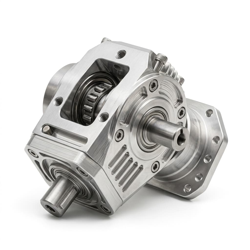
Generative Design & AI Parts: CNC Machinability and Cost Guide for Buyers
Evaluate generative design AI parts for CNC machinability, cost drivers, QA risk, hybrid routing, and DFM push-back before RFQ with supplier-ready checks.
By 2026, the adoption of AI-driven generative design and topology optimization in mechanical engineering has fundamentally reshaped how hardware is developed. Software platforms effortlessly calculate load paths and remove material where it is not strictly needed, yielding lightweight, highly efficient, "bionic" structures. For the engineering department, this is a triumph of mathematical optimization. For the procurement team, however, it is often the beginning of a sourcing nightmare.
When a buyer receives a drawing for a generative design part and sends it out to their traditional precision CNC machining supply base, the quotes that return are frequently shocking. A part that would traditionally cost $200 as a prismatic, blocky shape suddenly commands a quote of $1,200, accompanied by a 6-week lead time and a high risk of rejection. Many suppliers may simply issue a "No-Quote," citing a lack of capability.
The friction arises from a fundamental mismatch: generative design algorithms inherently favor additive manufacturing (3D printing) processes, producing complex, organic, free-form geometries. Yet, due to structural integrity requirements, material certification needs, or scale economies, engineering often demands that these parts be CNC machined from solid billets of aluminum, titanium, or stainless steel.
This comprehensive guide is designed for hardware buyers, procurement managers, and supply chain engineers who must bridge the gap between AI-optimized designs and the harsh realities of subtractive manufacturing. We will break down the specific cost drivers of organic geometries, explore how traditional Quality Assurance (QA) fails on these parts, provide a framework for evaluating hybrid manufacturing strategies, and equip you with a Design for Manufacturability (DFM) checklist to push back on overly complex engineering requirements before issuing an RFQ.
Scope, Date, and Limitations
This guide was published on July 23, 2026, targeting procurement professionals in the aerospace, robotics, automotive, and high-performance industrial sectors. It focuses primarily on the transition from AI-generated CAD models to subtractive CNC machining in low-to-medium volumes (10 to 5,000 units).
The multipliers and frameworks provided are illustrative guidelines intended for early-stage supplier negotiations and internal DFM triage. Actual costs will vary heavily based on the specific material grade, local labor rates, machine availability, and the required certification level (e.g., AS9100). This guide is not a substitute for a direct consultation with our application engineering team regarding your specific STEP or IGES files.
Related reading paths: Engineer-Reviewed DFM, Complex CNC Prototype Manufacturing, Motion Hardware Hub.
The Subtractive Reality: Why Organic Shapes Explode CNC Costs
To negotiate effectively with both your engineering team and your supply base, you must understand exactly why an AI-optimized shape drives up CNC machining costs. The challenges fall into three primary categories: Workholding, Tool Access, and Volumetric Removal.
1. The Workholding Dilemma (How do you hold a cloud?)
Standard CNC machining relies on flat, parallel, or perpendicular surfaces (datums) to grip the raw material securely in a vise. A traditional prismatic part has obvious flat sides. A generative design part often looks like a piece of coral or a twisted bone, featuring continuous organic curves with zero flat surfaces.
If there are no flat surfaces to grip, the CNC supplier is forced to design and machine custom "soft jaws" (custom-shaped vise jaws that match the part's contour) or build complex encapsulation fixtures. In extreme cases, the part must be encased in a sacrificial low-melting-point alloy or wax just to hold it during the final machining operations. This adds significant upfront NRE (Non-Recurring Engineering) costs and delays production kickoff.
2. Tool Access and 5-Axis Mandates
Generative algorithms frequently create undercuts, deep hollows, and sweeping web structures. A standard 3-axis CNC machine can only cut straight down from the top. To reach underneath an overhang or machine a complex sweeping web, the tool must approach from multiple angles simultaneously.
This mandates the use of highly expensive 5-axis CNC machining centers. While 5-axis machines are incredible pieces of technology, their hourly rate is typically double or triple that of a 3-axis machine. Furthermore, because the cutting tool must navigate deep into organic crevices, suppliers must use long, slender end mills. Long tools vibrate (chatter) easily, forcing the machinist to drastically reduce the cutting speed (feed rate) to maintain surface finish and dimensional accuracy.
3. The Interpolation Penalty and Surface Finish
When machining a flat plane, a CNC machine simply moves in a straight line (G01 code). When machining an organic, bionic curve generated by AI, the machine must read hundreds of thousands of microscopic, distinct coordinates to approximate the curve (a process called interpolation).
To achieve a smooth surface finish (like an Ra 0.8 or Ra 1.6) on a generative shape, the machine must use a ball-nose end mill and make thousands of tiny, overlapping passes—often referred to as 3D surfacing. A surface that would take 2 minutes to face-mill on a prismatic part can easily take 45 minutes of 3D surfacing to achieve the same surface roughness on an organic contour. This spindle time translates directly into piece-price escalation.
Prismatic Machining vs. 5-Axis Generative Surfacing
Traditional parts utilize rapid, linear material removal. Generative shapes force the machine into slow, complex 3D surface interpolations from multiple angles, exploding spindle time.
The Generative Geometry Cost Multiplier Matrix
To help procurement teams quantify the financial impact of specific generative design features, we have developed the Generative Geometry Cost Multiplier Matrix. Use this table when reviewing an AI-optimized design to identify the largest cost drivers and propose actionable DFM alternatives to your engineering team.
| Generative Feature Constraint | Standard CNC Baseline | Generative Cost Impact | Primary Cost Driver | Procurement DFM Push-back | Verification Impact |
|---|---|---|---|---|---|
| Zero Flat Outer Boundaries | Six orthogonal flat faces | 3.0x - 4.5x | Custom soft jaws, encapsulation fixturing, multiple setups. | Request addition of "sacrificial" flat tooling tabs that can be removed later. | Hard to establish part zero. |
| Deep Non-Standard Pockets | Floor depth < 3x tool dia. | 2.5x - 3.5x | Long slender tools causing chatter; requires slow feed rates. | Mandate minimum corner radii to allow larger, stiffer cutting tools. | CMM probe accessibility issues. |
| Undercuts & Sweeping Webs | Straight vertical walls | 4.0x - 6.0x | Forces 5-axis simultaneous machining and specialized lollipop cutters. | Ask if the undercut is structurally necessary or merely a software artifact. | Requires 5-axis scanning. |
| Fully Contoured Surfaces | Flat sealing planes | 3.0x - 5.0x | Extensive 3D surfacing time (ball-nose micro-stepping). | Convert non-critical organic surfaces back to flat prismatic planes. | Profile scanning needed. |
| Complex Intersecting Holes | Orthogonal bores | 2.0x - 3.5x | Drill wandering on angled entries; risk of burrs at organic intersections. | Ensure all hole entries start on a locally flat, perpendicular boss. | High risk of hidden burrs. |
| Organic Thin-Wall Struts | Uniform wall thickness | 3.5x - 5.5x | Machining vibration destroying thin webs; high scrap rate. | Thicken webs or redesign as a truss structure using standard dimensions. | Wall thickness variation high. |
The Quality Assurance (QA/QC) Nightmare
If machining a generative design part is difficult, inspecting it is arguably worse. Procurement teams must be hyper-vigilant about how these parts are dimensioned and toleranced before sending them to suppliers.
The Failure of Linear Tolerances
Traditional mechanical drawings rely heavily on linear tolerances (e.g., the distance from Face A to Hole B is 50.0mm ±0.1mm). However, on a generative part, "Face A" doesn't exist; it's a continuously sweeping curve. If an engineer attempts to apply standard linear dimensions to organic shapes, they are creating ambiguous, un-inspectable features.
When a CNC supplier receives a drawing full of ambiguous linear dimensions on organic curves, they will either reject the RFQ entirely, or they will price in massive risk premiums assuming a high likelihood of disputes during First Article Inspection (FAI).
The Necessity of Profile Tolerances and CMMs
For generative parts, engineering must abandon linear dimensions and embrace Geometric Dimensioning and Tolerancing (GD&T)—specifically Profile of a Surface. A Profile tolerance dictates that the entire sweeping surface of the part must fall within a defined 3D boundary (a "tolerance envelope") relative to the CAD model.
To inspect a Profile of a Surface tolerance, the supplier cannot use micrometers or calipers. They must use an advanced Coordinate Measuring Machine (CMM) or a high-end structured light optical scanner to generate a digital point cloud of the physical part and overlay it against the original STEP file. This requires expensive metrology equipment, highly trained quality technicians, and significant inspection time—all of which are billed to the buyer. If the drawing specifies a tight profile tolerance (e.g., Profile 0.05mm) across an entire bionic structure, you are virtually guaranteeing a multi-thousand-dollar unit cost.
Hybrid Manufacturing: Additive vs. Subtractive Break-Even
As AI generative design pushes the limits of what CNC machines can economically produce, procurement teams must evaluate Hybrid Manufacturing strategies or direct Metal 3D Printing (like DMLS - Direct Metal Laser Sintering).
The decision between CNC machining a generative part from a solid billet versus 3D printing it is a complex calculation of volume, material, and required precision.
- Volume Break-Even: 3D printing has zero tooling/fixturing cost but a very high, flat marginal cost per unit. 5-Axis CNC has high NRE (programming and fixturing) but the marginal cost drops with volume. For highly complex generative titanium parts, DMLS is often cheaper for quantities of 1 to 50. For volumes exceeding 100-200 units, the speed of CNC machining usually overtakes the additive process.
- The Hybrid Approach: The most pragmatic, cost-effective solution for generative parts is often hybrid. The complex, organic macro-structure is 3D printed (near-net shape) or investment cast. Then, the critical mating surfaces, bearing bores, and threaded holes are CNC machined to tight tolerances. Procurement should actively propose this hybrid route when quotes for "machined from solid" come back unacceptably high.
The Buyer's Generative Design Machinability Checklist
Before accepting a generative design CAD model from engineering and distributing it for RFQ, procurement and sourcing engineers must perform a triage audit. Use this checklist to challenge the design and strip out unnecessary cost drivers:
- 1. Tooling / Fixturing Tabs: Has engineering added localized, flat, parallel "tooling tabs" to the model to allow standard vise gripping? (These can be machined off later).
- 2. Flat Bounding Boxes: Can the overall outer boundary of the part be contained within a standard rectangular billet without excessive 5-axis undercutting on the perimeter?
- 3. Localized Flat Bosses for Holes: Do all drilled or tapped holes enter the part on a surface that is perfectly flat and perpendicular to the drill axis? (Drilling into an angled or organic face causes tool deflection and breakage).
- 4. Standardized Radii: Have all internal corner radii been standardized and sized to allow the largest possible end mill to reach the deepest pocket?
- 5. Profile Tolerance Zoning: Instead of applying a blanket, tight Profile tolerance over the entire organic part, has engineering loosened the tolerance on non-critical bionic webs (e.g., Profile 0.5mm) while maintaining tight controls only on critical mating features?
- 6. Surface Finish Reality Check: Are there demands for Ra 0.8 or finer on complex organic sweeps? Force engineering to accept Ra 3.2 or rougher on non-mating generative surfaces to eliminate hours of 3D ball-nose surfacing time.
- 7. Hybrid Feasibility: For titanium or super-alloys, has a near-net-shape additive (DMLS) or casting approach been formally evaluated before demanding 100% subtractive CNC?
Frequently Asked Questions (FAQ)
Q: Why does the CNC supplier charge an NRE fee for a part that was designed by AI to be "optimized"?
A: The AI optimized the part for weight and stress distribution in its final state, not for the subtractive manufacturing process. The NRE fee covers the extensive CAM (Computer-Aided Manufacturing) programming time required to generate 5-axis toolpaths and the physical cost of machining custom soft-jaws to hold the organic shape securely.
Q: Our engineers used a generative software that claims the part is "CNC ready." Why are quotes still so high?
A: Many software platforms allow engineers to constrain the AI solver to "3-axis" or "2.5-axis" capabilities. However, if the engineer prioritizes maximum weight reduction, the software will push the limits of those constraints, creating incredibly deep pockets or thin walls that technically can be reached by a tool, but are practically a nightmare due to vibration and chatter. "Possible to machine" is very different from "economical to machine."
Q: Can we just use a 3D scanner to inspect these parts instead of a CMM to save money?
A: Optical and laser scanners are excellent for verifying the overall organic shape of a generative part against the CAD model. However, if the part features critical bearing bores, precision dowel pin holes, or tight-tolerance sealing faces, scanners often lack the volumetric accuracy required. A combination of scanning for the organic body and tactile CMM probing for the critical features is usually required.
Q: If we switch to DMLS (Metal 3D Printing), do we completely eliminate CNC machining?
A: Almost never. Additive manufacturing cannot achieve the tight tolerances or fine surface finishes required for precision mechanical assemblies. Even if you 3D print the bionic structure, you must still mount it in a CNC machine to finish the critical mating surfaces. This is why hybrid manufacturing is the industry standard for generative hardware.
Sources & References
To support your internal engineering discussions and DFM reviews, refer to these industry standards and manufacturing guidelines:
- ASME Y14.46-2022: Product Definition for Additive Manufacturing. This standard is critical for understanding how to properly dimension and tolerance complex, organic geometries that defy traditional linear metrology. https://www.asme.org/codes-standards/find-codes-standards/y14-46-product-definition-additive-manufacturing-%281%29
- Society of Manufacturing Engineers (SME): Offers extensive technical papers on 5-axis toolpath optimization, chatter prediction in thin-wall machining, and the economics of hybrid manufacturing. https://www.sme.org/
- ISO 1101:2017 Geometrical Product Specifications (GPS): The foundational global standard for GD&T, vital for understanding how Profile of a Surface tolerances are defined and verified on free-form geometries. https://www.iso.org/standard/59536.html
Your Next Steps: De-Risking Generative Procurement
Procurement teams are on the front lines of the collision between advanced AI engineering software and the physical realities of the machine shop floor. Accepting un-optimized generative designs without a formal DFM review is a guaranteed path to blown budgets and supply chain delays.
Before you send your next batch of bionic, AI-generated components out for quote, engage with a manufacturing partner who understands both the digital and the physical realms of precision hardware.
At Linkup Precision, our engineering and procurement support teams specialize in bridging this gap. We routinely review complex generative CAD models, proposing specific, geometry-level DFM modifications that drastically reduce 5-axis spindle time and fixturing complexity without compromising the part's optimized load path. Whether your project demands pure 5-axis CNC from solid billet or a hybrid additive-subtractive approach, we provide clear, costed options.
Don't let software-generated complexity ruin your unit economics. Contact our engineering team today for a comprehensive DFM and machinability review of your generative components, and regain control of your procurement budget.
Author

Categories
More Posts
Two-Phase D2C Cold Plate CNC DFM Playbook for AI Rack Programs
A practical DFM and validation checklist for two-phase D2C cold plate machining, from micro-channel geometry to leak-test acceptance criteria.
Humanoid Linear Actuator Enclosure DFM and Acceptance Workflow
Execution workflow for humanoid actuator enclosure machining with fit-critical interfaces, tolerance management, and validation checkpoints.
MOFCOM-Compliant NdFeB Assembly Export Checklist for Robotics Programs
A practical checklist for exporting magnetic assemblies from China with fewer delays, covering scope definition, document packs, and handoff timing.