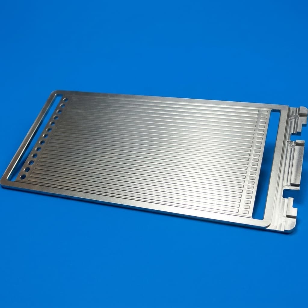
OFHC Copper C10100 Microchannel Cold Plate Machining & Diffusion Bonding: A Buyer’s DFM Guide
Source OFHC copper C10100 microchannel cold plates: compare machining routes, bonding risks and inspection evidence. Use the DFM checklist to prepare your RFQ.
Published and technically reviewed: 26 October 2026. Topic: Precision Machining. Region: Global. Audience: thermal engineers, NPI buyers, and drawing-release teams.
For OFHC copper C10100 microchannel cold plate machining and diffusion bonding, the buying decision is whether a supplier can preserve channel geometry while producing a qualified, leak-tight joint. Specify the exact alloy, compare machining routes against the drawing, and agree on inspection evidence before comparing piece prices.
C10100 is the oxygen-free electronic (OFE) designation; “OFHC” alone is not an adequate purchase-order callout. Diffusion bonding can join a machined base and cover without filler metal, but it does not automatically eliminate bond defects, thermal resistance, or coolant leaks. A qualified assembly needs evidence for both bond integrity and open flow paths.
Use this guide with our precision CNC machining scope and cold plate interface machining scope. To start a DFM discussion, send the drawing, coolant, and operating envelope.
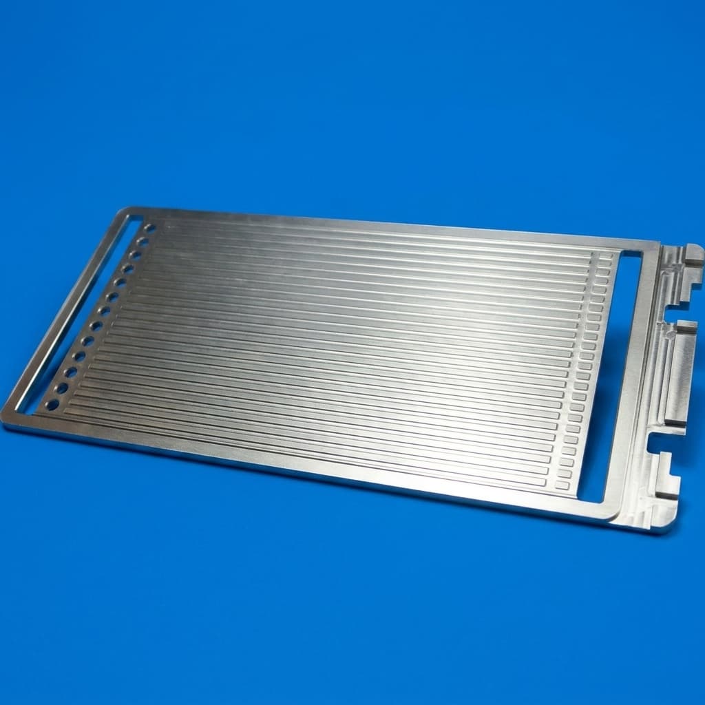
Illustrative geometry only. This image does not establish C10100 composition, dimensions, diffusion-bond quality, or measured cooling performance.
Scope and Engineering Boundaries
This guide covers CNC micro-milling, gang slitting, etched laminates, skived fins, surface preparation, and solid-state diffusion bonding of copper cold plate bodies and covers.
- Applicable decisions: alloy callout, process selection, pre-bond geometry, supplier qualification, and RFQ acceptance evidence.
- Cooling limits: single-phase and two-phase designs require separate working-fluid, pressure, thermal, and corrosion qualification. An approval with water does not transfer to a refrigerant or dielectric fluid.
- Customer responsibility: heat load and heat flux, coolant chemistry, operating and transient pressure, allowable pressure drop, mounting loads, and system-level thermal validation.
- Supplier responsibility: material traceability, machining and cleaning plans, bonding-process qualification, inspection coverage, and traceable records. Identify the bonding operator and any external test laboratory in the quote.
Evidence boundary: material identification below comes from the CDA record; joining principles come from TWI. The process matrix, worked calculations, and RFQ checklist are engineering decision aids, not factory trial results, customer case studies, or guaranteed production capabilities. No universal channel-size, furnace-cycle, or leak-rate specification is established here.
1. Material Metallurgy: When to Specify UNS C10100
The Copper Development Association C10100 record identifies OFE copper with minimum 99.99% copper, maximum 0.0005% oxygen (5 ppm), and minimum 101% IACS conductivity in the annealed condition. Apply the record's composition footnotes and the purchase specification when checking a mill certificate.
C10100 is appropriate when the drawing requires that purity and conductivity. C10100 is not the only copper grade that can be diffusion bonded. C10200 is another oxygen-free grade that may be evaluated, but substitution requires the design authority's approval and qualification of the actual material, surface condition, and joining route. C11000 is a distinct grade and must not be treated as an interchangeable “pure copper” substitute.
Copper Grade Procurement Benchmark
| Procurement question | C10100 / OFE | C10200 / OF alternative | Drawing or RFQ action |
|---|---|---|---|
| Exact identity | Explicit UNS designation | Separate UNS designation | Reject an unspecified “OFHC” callout |
| Purity requirement | 99.99% minimum, subject to composition footnotes | Verify its own grade specification | Match the certificate to the released alloy |
| Oxygen requirement | 5 ppm maximum | Verify its own oxygen limit | Request traceable chemistry evidence |
| Conductivity | 101% IACS minimum in annealed condition | Check grade and material condition | Conductivity alone does not certify chemistry |
| Stock form | Specify plate, bar, sheet, or billet | Specify the actual supplied form | Select a standard covering that product form |
| Temper | Define incoming and post-bond condition | Qualify the proposed condition | Evaluate distortion and final strength |
| Joining acceptance | Requires process qualification | Requires separate substitution approval | Request representative bond coupons |
| Commercial comparison | Obtain a current stock quote | Quote only as a declared alternative | Compare equivalent inspection and delivery scope |
Product-form caution: ASTM B170 covers oxygen-free copper wire bars, billets, and cakes; it is not a universal finished-plate purchase specification. Ask the supplier to identify the applicable current standard, edition, product form, and temper. A mill certificate establishes material traceability; it does not establish a qualified diffusion-bonded assembly.
2. Microchannel Machining: Comparing the Four Manufacturing Routes
Start with channel width and depth, fin thickness, header geometry, and which lands must bond to the cover. A channel aspect ratio (depth divided by channel width) and a fin aspect ratio (fin height divided by fin thickness) describe different constraints; quote both.
The matrix below is a qualitative screening framework. Minimum feature size, cycle time, tooling cost, and yield must come from a supplier trial on representative geometry rather than a generic process label.
| Evaluation dimension | CNC micro-end milling | Multi-blade gang slitting | Photochemical etching | Skiving |
|---|---|---|---|---|
| Best initial fit | Complex channels and integrated headers | Repeated straight channels | Patterned sheet laminates | Repeated integral fins |
| Geometric freedom | Tool-accessible curves and pockets | Primarily straight cuts | Planar patterns per layer | Constrained by skiving direction |
| Depth control | Tool reach and deflection matter | Blade reach and runout matter | Etch depth and undercut matter | Fin formation and base thickness matter |
| Burr or edge risk | Tool wear, rubbing, and exit burrs | Entrance and exit burrs | No cutting burr, but edge undercut | Edge condition and fin deformation |
| Bond-face preparation | Verify rib height after finishing | Verify after sawing and deburring | Control cleanliness and stack registration | Qualify fin-top height and contact |
| Setup trade-off | Flexible programming; small-tool wear | Arbor and blade setup | Phototool and laminate registration | Dedicated forming setup |
| Scaling question | Demonstrate repeatable tool life | Demonstrate pitch and blade stability | Demonstrate stacked yield | Demonstrate fin uniformity |
| Qualification evidence | Sectioned pilot and dimensional map | Burr map and channel consistency | Etch profile and bonded-stack sections | Fin profile and post-bond sections |
Selection rule: shortlist micro-milling for complex NPI geometry, gang slitting for straight arrays, and etched laminates when stacking is compatible with the flow design. Evaluate skiving only with a demonstrated cover-joining plan. Annual volume alone cannot establish the cheapest route; compare setup amortization, accepted-part yield, and inspection cost.
3. The Micro-Burr Dilemma and Removal Protocol
Burrs can obstruct channels or hold bonding lands apart. Aggressive brushing, blasting, or tumbling can deform slender fins, so qualify any removal method on representative parts before approving it.
Four Steps to a Bond-Ready Surface
- Control burr formation during cutting. Request the tool geometry, wear limit, cutting strategy, and supported-fin approach. Inspect the first and last parts in a tool-life trial; a sharp first-part result does not establish batch consistency.
- Qualify temporary support materials. If wax or soluble support is proposed, require a removal and residue-verification method. A material that supports machining may still contaminate a bond surface or coolant path.
- Measure deburring stock loss. Chemical or electrochemical methods can change fin thickness, channel width, and edge radius. Record dimensions before and after treatment instead of assuming selective burr removal.
- Verify the final bonding lands. Specify datum, inspected area, surface texture, flatness, cleaning sequence, and maximum storage interval before bonding. A finishing method's name does not guarantee contact quality.
Worked tolerance example, not a recommended etch recipe: if a treatment removes 3 µm from each side of a 0.180 mm fin, the remaining thickness is 0.174 mm. A channel bounded by two treated walls widens by 0.006 mm. Include that change in the drawing tolerance budget and verify it by measurement.
4. Solid-State Vacuum Diffusion Bonding: Qualification and Failure Modes
TWI's diffusion bonding process explanation describes a solid-state process using elevated temperature, pressure, and controlled atmosphere. For similar materials, a joint can be made without filler; surface roughness and flatness influence contact and bond quality.
A furnace schedule must be qualified for the actual alloy, surface preparation, geometry, fixture, and batch arrangement. There is no universally valid temperature-pressure-time recipe for C10100 microchannels. Ask for the following evidence rather than copying a generic furnace window:
- Atmosphere: recorded vacuum or inert-gas conditions, cleanliness controls, and leak/outgassing checks appropriate to the process.
- Temperature and time: part-representative temperature records, uniformity evidence, soak definition, and controlled cooling.
- Load: applied force, reference area, platen alignment, fixture load path, and displacement history.
- Geometry retention: pre/post-bond channel and fin measurements, distortion, and port/mounting-datum checks.
- Bond performance: representative sections or mechanical coupons, plus the agreed leak, flow, and thermal tests.
The Channel Collapse versus Bond Integrity Trade-off
Illustrative load-area calculation: consider a repeating cell with a 0.15 mm rib and a 0.30 mm channel. If only the rib tops carry a uniformly distributed load, the contact fraction is 0.15 / (0.15 + 0.30) = 1/3. Average rib stress is therefore approximately three times pressure calculated over the full projected core area.
This simple model excludes perimeter lands, cap bending, fixture load paths, creep, and buckling. It flags a question for the bonding specialist; it cannot approve a furnace pressure or a maximum fin aspect ratio. Ask whether the quoted “bonding pressure” uses projected area or actual contacting land area.
A proposed fin height of 2.20 mm and thickness of 0.18 mm gives a fin aspect ratio of approximately 12.2:1. That calculation is reproducible; its structural acceptability is unresolved until the actual process is qualified. Supports or mechanical stops require trials, and any internal support needs a demonstrated removal and cleanliness plan.
Before approving the pilot, request a DFM review of the load path and acceptance plan.
5. Visual: Diffusion Bonding NPI Control Loop
Conceptual qualification workflow, not measured production data. Read the gates as material → machining → bond-surface preparation → joining → assembly validation. Numeric acceptance limits belong in the approved project plan.
6. Quality Assurance and Non-Destructive Examination
Leak tightness, bond strength, and channel performance are different acceptance questions. No single inspection establishes all three. The following six gates define evidence to agree before manufacture; they do not prescribe universal pass thresholds.
| Inspection gate | Method to agree | Acceptance basis | Interpretation and limitation |
|---|---|---|---|
| Incoming material | Mill certificate and specified chemistry checks | Released UNS grade, stock form, temper, and purchase standard | Conductivity screening alone cannot prove full composition |
| Pre-bond surfaces | Optical or contact metrology with suitable access | Drawing-defined flatness, texture, burr, and cleanliness limits | Measure in a defined support condition; clamping can mask distortion |
| Bond interface | Qualified ultrasonic/SAM procedure plus representative destructive coupons | Demonstrated detection capability and project defect criteria | Small or closed defects may escape detection; geometry can mask indications |
| Channel flow | Measured flow-pressure curve at defined fluid and temperature | Agreed baseline, tolerance band, and fixture-loss correction | High or low pressure drop is a symptom, not unique proof of a cause |
| Pressure containment | Controlled proof-pressure test under an approved procedure | Design authority's pressure, duration, temperature, and applicable code | A proof pass does not establish fatigue life or thermal performance |
| External leak tightness | Calibrated helium or other agreed leak method | Stated gas, pressure differential, detection mode, sensitivity, and leak limit | External leak testing does not establish absence of internal bypass |
TWI's technical review of diffusion bonding describes dedicated work to validate ultrasonic detection of diffusion-bond defects. Do not assume a generic acoustic scan can detect every weak or “kissing” bond. Establish capability with representative reference defects and correlate with destructive evidence where needed.
Do not attach a general ASME or ASTM label to a leak limit, proof-pressure multiplier, or allowable void percentage. The design authority must establish code applicability and the specific method and edition; a standards publisher's homepage is not evidence that a test plan meets that code.
7. The 10-Point Procurement and Drawing Release Checklist
- 1. Alloy and traceability: state UNS grade, product-form standard and edition, temper, certificate requirements, and whether alternatives require written approval.
- 2. Cleanliness: define permitted machining/support materials, removal methods, residue or particle limits, and protection before bonding.
- 3. Channel and fin geometry: separate channel width/depth from fin thickness/height, with tolerances and agreed inspection access.
- 4. Tool access and load paths: review header radii, fragile fins, perimeter lands, cap thickness, and the supplier's support/fixture proposal.
- 5. Bonding lands: define datum, inspected span, flatness, surface texture, and measurement support condition.
- 6. Plating and fluid compatibility: identify wetted surfaces, coating thickness, masking, rinse/dry verification, and coolant qualification. Do not approve inaccessible trapped chemistry.
- 7. Burr acceptance: define detectable burr size, inspection method/coverage, and dimensional allowance for any removal process.
- 8. Proof and leak tests: specify pressure, temperature, duration, gas, detection mode, leak-rate units, and calibrated method capability.
- 9. Bond and performance evidence: agree coupon/NDT correlation, sampling and lot containment, flow-pressure curves, and thermal validation conditions.
- 10. Packaging and release: agree cleanliness-compatible packaging, drying, traceability labels, storage conditions, and the complete release record. Qualify any corrosion inhibitor against the coolant path.
8. Commercial Sourcing Dynamics and RFQ Evaluation
Compare cost per accepted assembly. Ask bidders to separate material and scrap assumptions, machining setup, consumable tooling, cleaning, bond qualification, furnace batch loading, inspection, and rejected-part responsibility. Use dated, quantity-specific quotations rather than a generic copper price, fixed tool-consumption estimate, or promised cycle-time range.
A lower piece price may exclude the cover, bonding subcontractor, first-article sections, leak testing, or thermal validation. Normalize those inclusions before choosing a route. Ask for declared process changes when tooling, alloy source, furnace loading, or the bonding operator changes.
RFQ Input Data Fields
Copy this template and replace every REQUIRED value. The identifiers and geometry example are illustrative; they do not approve a design or test specification. Keep an RFQ open until the buyer and supplier have resolved all acceptance fields.
field,value,procurement_note
project_id,EXAMPLE-C10100-001,Replace with your revision-controlled identifier
part_description,Microchannel cold plate base and cover,Define supplied assembly scope
raw_material,UNS C10100 OFE copper,Specify product form and applicable purchase standard
material_temper,REQUIRED,Define incoming and post-bond requirements
channel_width_depth,REQUIRED,Provide drawing dimensions and tolerances
fin_thickness_height,0.18 mm and 2.20 mm example only,Fin aspect ratio approximately 12.2 requires qualification
coolant_temperature_range,REQUIRED,Include chemistry and single-phase or two-phase operation
heat_load_flux_and_mounting,REQUIRED,Define thermal validation and mounting boundary conditions
working_transient_pressure,REQUIRED,Design authority to define operating envelope
flow_pressure_drop_limit,REQUIRED,Specify fluid temperature and measurement conditions
bond_land_flatness_roughness,REQUIRED,Define datum span and metrology
joining_scope,Solid-state diffusion bonding proposed,Identify operator and qualification deliverables
helium_leak_test,REQUIRED,Specify mode gas pressure sensitivity and acceptance rate
proof_pressure_test,REQUIRED,Specify approved pressure duration temperature and procedure
bond_integrity_evidence,REQUIRED,Agree coupons NDT capability and acceptance criteria
pilot_and_annual_quantity,REQUIRED,Include schedule and accepted-part yield responsibility
Frequently Asked Questions (FAQ)
Can we use vacuum brazing instead of diffusion bonding?
Potentially. Brazing introduces filler and requires control of its flow, joint clearance, and compatibility with narrow channels. Diffusion bonding avoids filler but requires a qualified contact surface and load/temperature cycle. Compare assembly-level thermal, leak, fatigue, yield, and cost evidence; processor wattage alone does not select the joining route.
What causes microchannel fin waviness or bending during milling?
Possible causes include tool deflection, rubbing, built-up edge, inadequate support, and excessive cutting loads. Request a tool-life trial and inspect fin geometry before and after deburring. A tooling brand or coating does not establish capability on the released geometry.
Why does flatness change after removing the cold plate from a CNC fixture?
Clamping deformation or residual stress can make a part appear flat while restrained. Compare measurements in the specified free or supported condition and review the roughing/finishing sequence. Any proposed stress-relief treatment requires material and distortion qualification; there is no universal annealing schedule for this assembly.
Can copper microchannels be bonded to an aluminum cover?
Treat this as a separately qualified dissimilar-material joint. Review interface metallurgy, thermal-expansion mismatch, wetted-material corrosion compatibility, and any interlayer with the joining specialist. Approval of a copper-to-copper assembly does not transfer to copper-to-aluminum.
How do we detect internal bypass between flow passes?
An external helium test can pass even when flow bypasses an internal partition. Compare flow-pressure curves under controlled conditions and investigate anomalies with suitable imaging, sectioned samples, or other qualified tests. A low pressure drop alone does not prove bypass, and an acoustic scan alone does not prove its absence.
Sources and Applicability
Sources reviewed for this guide on 26 October 2026:
- Copper Development Association — C10100 alloy record. Basis for the OFE designation, composition limits, and annealed conductivity note. This material record does not qualify a supplier's stock or bonded assembly.
- TWI — Our Processes: Diffusion Bonding. Basis for the joining mechanism, contact-surface considerations, and controlled atmosphere. Its general process description is not a C10100 microchannel production recipe.
- TWI — Technical Insight: Diffusion Bonding. Background on process development and validation of ultrasonic inspection for diffusion-bonded structures. It does not establish universal defect acceptance limits.
The worked examples and procurement framework are editorial engineering guidance. Obtain the applicable current specifications and project-specific qualification records before drawing release.
Take the Next Step with Linkup Precision
Prepare your STEP model, revision-controlled drawing, coolant and pressure envelope, target flow-pressure curve, thermal requirements, quantity, and acceptance evidence. Contact Linkup Precision for a cold plate DFM review or review our thermal hardware machining scope.
Ask the quote to identify machining, bonding, and test responsibilities explicitly. Confirm the proposed production route and inspection capability during the review before releasing a pilot order.
Author

Categories
More Posts
Machining Invar & Kovar for Silicon Photonics - A DFM & Cost Guide
Learn why optical transceivers for AI data centers require ultra-low CTE alloys, and how to optimize Invar 36 and Kovar CNC machining for procurement cost.
PFAS-Free CNC Machining & Surface Finishes - 2026 Compliance Checklist
PFAS-free CNC machining checklist for auditing coolants, anodizing, cleaning, supplier records, and 2026 sourcing risk. Talk to Linkup Precision.
Frameless BLDC Motor Rotor & Stator Carrier Precision Machining: Air-Gap Stack-Up, Coaxiality, and Dynamic Balancing (ISO 21940)
Source frameless BLDC motor carriers with an air-gap budget, datum strategy, ISO 21940 balancing examples, and an RFQ checklist. Submit drawings for DFM review.