Frameless BLDC Motor Rotor & Stator Carrier Precision Machining: Air-Gap Stack-Up, Coaxiality, and Dynamic Balancing (ISO 21940)
Source frameless BLDC motor carriers with an air-gap budget, datum strategy, ISO 21940 balancing examples, and an RFQ checklist. Submit drawings for DFM review.
Published and reviewed: 02 November 2026. Topic: Precision Machining. Region: Global. Audience: robotics electromechanical engineers, motor architecture leads, joint actuator NPI managers, and precision hardware procurement specialists.
For frameless BLDC motor rotor and stator carrier precision machining, qualify three mechanical foundations before finalizing quotes or releasing tooling: the cumulative radial air-gap tolerance stack-up under operating thermal extremes, the dynamic unbalance allocation per ISO 21940-11 using dedicated balancing arbors, and the structural retention strategy (anaerobic retaining adhesive versus thermal shrink-fit). A supplier quoting a carrier as a generic turned ring without addressing concentricity datums risks delivering parts that induce destructive Unbalanced Magnetic Pull (UMP), premature bearing spalling, and acoustic whine in the final joint drive.
In frameless brushless motor kits (such as the Kollmorgen KBM Series Frameless Motors), the motor manufacturer supplies a stator and rotor for integration into the machine. The builder provides the housing and functional bearing support; the supplied rotor hub and required carrier interfaces depend on the selected kit drawing.
Use this procurement and DFM guide alongside our rotor and stator carrier manufacturing scope and precision CNC machining scope. To evaluate a custom carrier drawing or joint stack-up, submit your STEP model and tolerance envelope.
Scope and Engineering Boundaries
This guide supports drawing reviews, supplier capability audits, and RFQ preparation for metallic rotor and stator carriers deployed in robotics joint actuators, direct-drive rotary tables, surgical tools, and aerospace gimbals.
- Applicable decisions: establishing geometric dimensioning and tolerancing (GD&T) datums between bearing journals and magnet seats; selecting carrier alloys based on thermal expansion matching; defining single-plane versus two-plane dynamic balancing criteria; and agreeing upon first-article CMM inspection protocols under unrestrained free states.
- Design authority responsibility: specify electromagnetic motor parameters, nominal air-gap clearance, winding thermal class, bearing preload class, operational speed spectrum (
n_max), target balance quality grade (G), operating ambient temperature limits, and adhesive retaining specifications. - Supplier responsibility: execute lathe turning and 5-axis mill-turn sequences that prevent chuck-clamping lobing; qualify stress-relief thermal cycles; design precision balancing and grinding arbors; verify CMM true position, circularity, and runout; and provide traceable material and balance inspection certificates.
- Limits: no universal micron tolerance, press-fit interference, or balancing grade applies identically across all motor frame sizes. A 45 mm outer-diameter robotic wrist carrier operating at 3,000 RPM has fundamentally different centrifugal and thermal dynamics than a 180 mm direct-drive robotic torso motor operating at 800 RPM. Finished joint performance cannot be guaranteed without full assembly-level validation.
Evidence and method: this framework is an engineering procurement guide, not an assertion of Linkup standard catalog stock or measured customer results. The air-gap budget and balance table are worked examples, not measured capability or motor-vendor acceptance limits. ISO 21940-11 covers rotors with rigid behaviour; flexible-rotor behaviour requires a different assessment. Purchase orders must identify approved drawings and standard revisions, including applicable amendments. No compliance certification is implied.
1. The Physics of Air-Gap Stack-Up and Unbalanced Magnetic Pull (UMP)
Use the selected motor vendor's radial air gap and installation limits. This guide uses a nominal 0.500 mm gap solely to demonstrate a budget; it is not a range that applies to every frameless BLDC motor. Manufacturing variation, temperature, bearing motion, and load deflection must be assessed together.
The Mechanism of Unbalanced Magnetic Pull
In a perfectly concentric assembly, the radial magnetic forces exerted by high-energy NdFeB permanent magnets across the 360° air gap cancel symmetrically, resulting in zero net lateral force. However, when manufacturing runout, bearing play, or housing ovality causes the rotor centerline O_r to displace from the stator bore centerline O_s by an eccentricity distance e, the air gap becomes asymmetrical:
g(θ) ≈ g_0 - e cosθ
A narrower local gap can increase magnetic attraction and produce a net radial side-load, Unbalanced Magnetic Pull (UMP). Its magnitude depends on magnet geometry, steel saturation, winding current, and the magnetic circuit; an inverse-square gap rule alone cannot predict the force in a real motor.
UMP can reinforce eccentric displacement and increase bearing loads. Quantify force, vibration, and bearing-life consequences with motor-specific electromagnetic and structural analysis or measurements. This guide does not assign a universal side-load or life-reduction percentage.
+-----------------------------------------------------------------------------------+
|                        AIR-GAP BUDGET ALLOCATION (0.50 mm NOMINAL)                |
+-----------------------------------------------------------------------------------+
| [### Residual Geometric Gap: 0.375 mm (75.0%)                                  ] |
| [### Bearing Radial Motion Allowance: 0.008 mm (1.6%)                           ] |
| [### Bearing Axis Alignment Allowance (B): 0.012 mm (2.4%)                     ] |
| [### Stator Housing Bore Cylindricity & Ovality: 0.015 mm (3.0%)                ] |
| [### Rotor Pilot Radial Closure Allowance (C): 0.015 mm (3.0%)                  ] |
| [### Adhesive Assembly Offset: 0.025 mm (5.0%)                                 ] |
| [### Thermal Closure Allowance (assumed): 0.040 mm (8.0%)                       ] |
| [### Dynamic Whirl & Centrifugal Deflection: 0.010 mm (2.0%)                    ] |
+-----------------------------------------------------------------------------------+
Cumulative Air-Gap Tolerance Budget Table
The following illustrative budget starts with a nominal 0.500 mm radial gap. All contributions are assumed one-sided radial closure allowances added conservatively in the same direction. The third column lists individual contributions, not running subtotals. It does not convert every form tolerance or TIR directly into eccentricity: pure circular offset gives eccentricity = TIR/2, while form errors require a separate envelope. The thermal allowance is independent of the diametral fit example in Section 3. Avoid double-counting correlated errors in a real stack.
| Error Vector Source | Illustrative Allowance Range | Radial Closure Contribution | Critical Procurement & DFM Safeguard |
|---|---|---|---|
| Bearing Internal Play & Runout | 0.004–0.010 mm | 0.008 mm | Obtain installed radial motion from bearing arrangement, fits, preload, and temperature. Precision class alone does not define play. |
| Bearing Journal Coaxiality (Datum B) | 0.008–0.015 mm | 0.012 mm | Single-setup turning/grinding of dual bearing journals to eliminate rechucking runout. |
| Stator Housing Bore Form | 0.010–0.020 mm | 0.015 mm | Specify circularity/cylindricity separately from the ISO size fit; inspect thin-wall distortion after unclamping. |
| Rotor Magnet Pilot Radial Envelope (Feature C) | 0.010–0.018 mm | 0.015 mm | Derive radial closure from permitted TIR and form error relative to the bearing axis; do not treat these as interchangeable. |
| Adhesive Assembly Offset | 0.020–0.035 mm | 0.025 mm | Control alignment during cure; diametral clearance alone does not locate the rotor. |
| Thermal Gap Closure | 0.025–0.055 mm | 0.040 mm | Calculate actual radial rotor/stator growth at their respective temperatures; this is a placeholder allowance. |
| Rotor Shaft Dynamic Deflection | 0.005–0.015 mm | 0.010 mm | Maximize shaft section modulus; prevent operating near first critical bending speed. |
| Total Assumed Consumption | — | 0.125 mm (25.0%) | Leaves 0.375 mm geometric clearance in this example, before any additional required margin. |
Arithmetic: 0.008 + 0.012 + 0.015 + 0.015 + 0.025 + 0.040 + 0.010 = 0.125 mm; 0.500 − 0.125 = 0.375 mm. A positive result is a geometric screen, not motor approval. Release requires vendor minimum-gap limits, coating allowance, assembly verification, and operating-load validation.
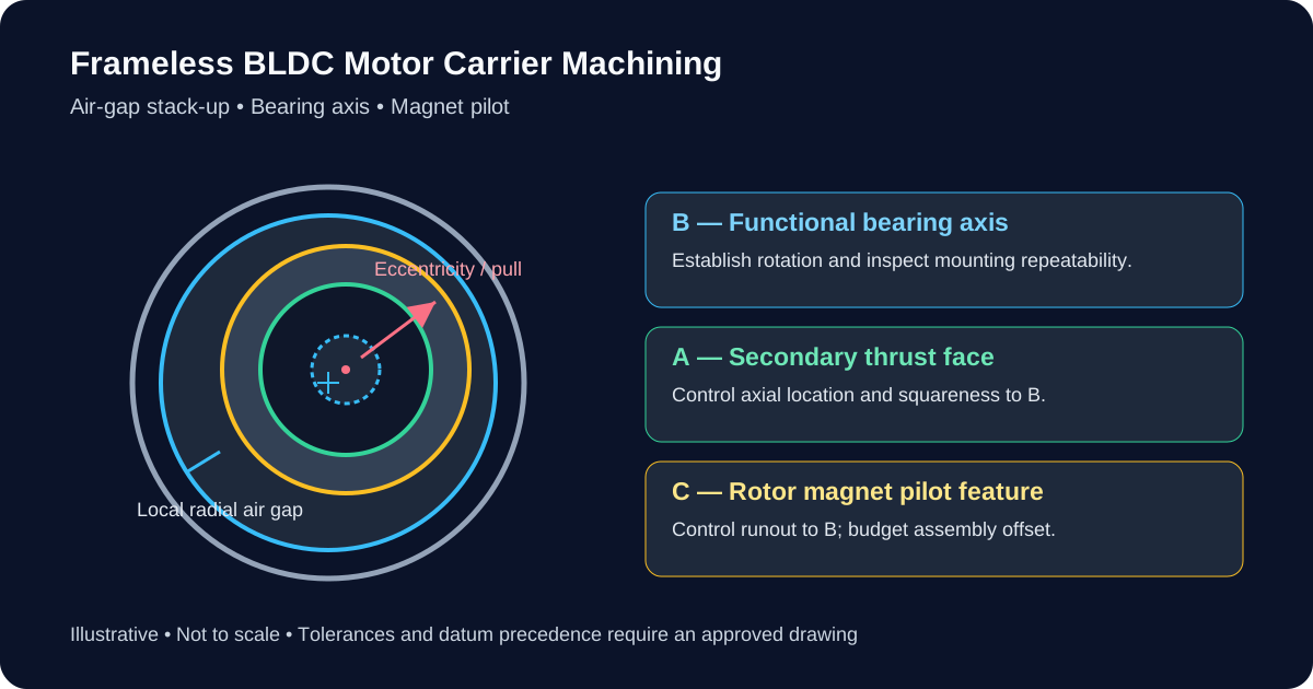
2. Visual: Air-Gap Eccentricity and Geometric Datum Architecture
The diagram illustrates a functional datum strategy for drawing review. The bearing axis B and thrust face A are separate datum features; the controlled pilot C is not automatically a datum:
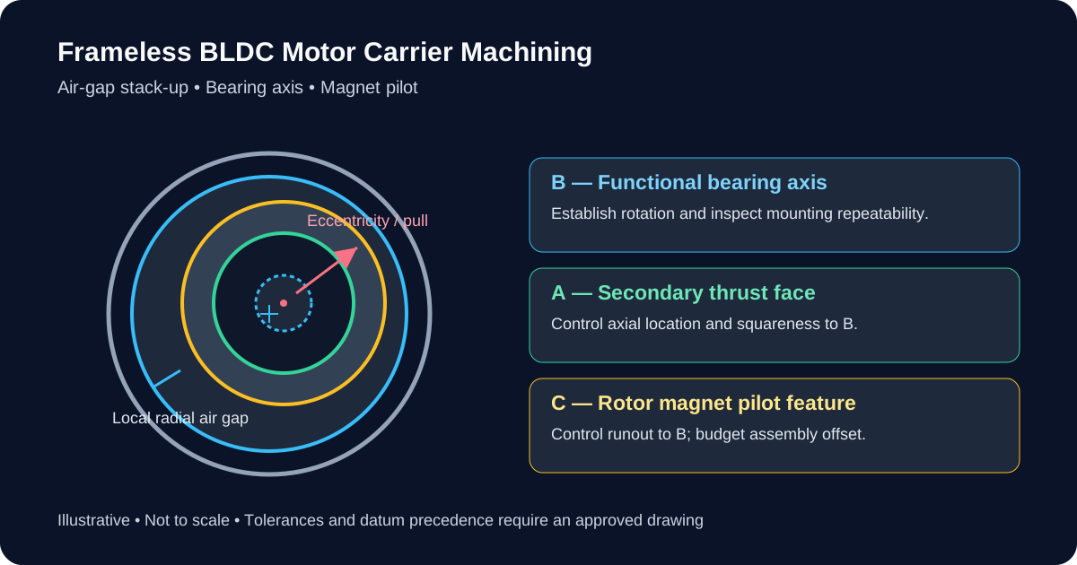
Illustrative cross-section, not to scale. B establishes the bearing axis; A is the secondary axial locating face. C identifies the controlled pilot feature. Datum precedence and numeric tolerances must follow the approved drawing.
3. Metallurgy: Carrier Material Selection and Thermal Expansion Matching
Choosing the carrier alloy requires balancing weight, structural stiffness, machinability, and—most importantly—the Coefficient of Thermal Expansion (CTE) relative to adjacent motor sub-components.
Electrical-steel laminations, magnets, sleeves, and adhesives respond differently to temperature. Magnet expansion can be anisotropic; obtain grade-specific properties and operating temperatures rather than using a single magnet CTE in every direction.
Carrier Material Trade-off Matrix
The values below are approximate screening inputs, not material acceptance data. Obtain alloy-, temper-, product-form-, and temperature-specific values from the supplier; specify the governing material standard on the drawing.
| Alloy / Condition to Confirm | Approximate CTE (10⁻⁶/K) | Approximate Density (g/cm³) | Carrier Selection Trade-off |
|---|---|---|---|
| 6061, approved stress-relieved temper | 23–24 | 2.70 | Light and readily machined; an aluminum housing expands more than a steel stator at equal temperature. |
| 7075, approved stress-relieved temper | 23–24 | 2.81 | Higher strength can help stressed interfaces; elastic stiffness is similar to 6061, so strength alone does not prevent deflection. |
| AISI 4140, specified Q&T condition | 12–13 | 7.85 | Closer expansion match to steel laminations; ferromagnetism must be assessed in the magnetic circuit and sensor layout. |
| 17-4PH, specified aging condition | 10–12 | 7.8 | Corrosion resistance and lower expansion; magnetic behaviour and strength depend on condition. |
| Ti-6Al-4V, specified condition | 8–9 | 4.43 | Lower mass than steel and lower expansion; a titanium housing around steel may tighten as both heat. Machining cost is higher. |
The Thermal Mismatch Dilemma: Aluminum vs. Silicon Steel
For this separate fit example, assume both components heat uniformly from 20°C to 80°C (ΔT = 60 K), with constant illustrative CTE values. Real part temperatures may differ substantially.
If an aluminum stator sleeve (6061-T651) surrounds an 80 mm outer-diameter silicon steel stator stack:
ΔD = D₀ × (α_Al − α_steel) × ΔT
ΔD = 80 mm × (23.4 − 12.0) × 10⁻⁶/K × 60 K ≈ 0.055 mm (55 µm)
Under these equal-temperature, freely expanding assumptions, a 0.020 mm cold diametral interference would be lost. Actual retention depends on contact stiffness, temperature gradients, and other locating features. Increasing cold interference can introduce damaging stress, so check lamination limits and the torque path before selecting it. The 0.055 mm result is a diametral interface change; it is not automatically radial electromagnetic gap closure.
Drawing decision: compare a qualified adhesive joint, an engineered interference fit, or a mechanically retained intermediate sleeve. ISO 286-1 defines linear-size fit concepts; it does not set form, coaxiality, or adhesive clearance. H6/js6 is a transition fit and must not be called a guaranteed slip-fit. Calculate actual minimum and maximum clearance at the nominal diameter and temperatures.
4. Thin-Wall Lathe Turning and Clamping Physics
Thin carrier walls reduce mass and can lower rotational inertia. For a uniform hollow cylinder about its axis, J = (m/2) × (r_outer² + r_inner²); thin-ring inertia approaches m × r². Tight runout and form requirements on these shells make clamping distortion a key process risk.
The Tri-Lobe Distortion Pitfall
When a standard 3-jaw lathe chuck grips a thin-walled aluminum or steel cylinder, radial clamping forces deform the ring into a three-lobed (tri-oval) shape during cutting. The lathe tool cuts a geometrically true round path while the component is clamped under strain.
Once the chuck jaws release the finished part, the material elastically rebounds:
[Clamped State Under 3-Jaw Chuck]            [Released Unrestrained State]
        Radial Force P                                  Lobe 1
             │                                            ▲
        ▼─────────▼                                     /   \
     ▲               ▲                                 /     \
    /                 \                             ◄──       ──►
   │      CUT PATH     │     == Released ==>      Lobe 3       Lobe 2
    \   (Appears True) /                               \     /
     ▼─────────▼                                        \   /
             ▲                                            ▼
An unrestrained inspection can reveal lobing hidden by chuck pressure. Its magnitude depends on wall thickness, jaw contact, clamping load, and residual stress. Compare free-state and functionally restrained measurements where both affect acceptance.
Production Routing Strategies for Distortion Control
For a drawing requiring single-digit-micron form control, qualify the process on representative parts rather than assuming a fixture guarantees capability:
- Distributed soft-jaw contact: use bored soft jaws or a suitable collet to spread load. Record clamping pressure and check geometry after unclamping; do not assume a fixed percentage improvement.
- Expanding mandrel: reference the finished functional bore when appropriate. Qualify expansion-induced distortion, seating repeatability, and runout after remounting.
- Staged machining: rough with geometry-specific stock allowance, allow stabilization, and measure before finishing. Any thermal stress-relief cycle must be approved for the alloy and temper; a generic 160°C/3 h cycle is not a universal anneal and may alter precipitation-hardened properties.
- Finish and verify: choose PCD tooling for suitable aluminum alloys or a qualified grinding/turning route for the selected material. Record inspection temperature, soak time, fixture state, and measurement uncertainty.
5. Dynamic Balancing Architecture: ISO 21940-11 Protocols
A vendor may balance a rotor subassembly on suitable tooling before delivery. That result does not establish the balance of the customer's completed hub, magnets, sleeve, and fasteners. Define the final assembly state and functional axis for acceptance, and verify balance after operations that change mass distribution.
Permissible Residual Unbalance Mathematics
Balancing rigid rotors is governed globally by ISO 21940-11:2016 (which superseded the legacy ISO 1940-1 standard). The fundamental formula connects balance quality grade (G), rotor mass (M in kg), and maximum operating rotational speed (n in RPM):
U_per = (9549 · G · M)/(n)
Where:
U_peris the total permissible residual unbalance in gram-millimeters (g·mm).Gis the balance quality grade in millimeters per second (mm/s).Mis the total finished rotor assembly mass in kilograms (kg).nis the maximum operating service speed in revolutions per minute (RPM).
To express the residual-unbalance allowance as an equivalent point mass (m_per in grams) at radius (r in mm):
m_per = (U_per)/(r)
Permissible Residual Unbalance (U_per) Reference Table
The table compares two candidate grades using assumed masses and service speeds. Application labels are illustrative, not ISO grade recommendations. Values are total assembly allowances rounded to two decimals; the equivalent point masses use unrounded values. This is a rigid-rotor calculation and does not allocate tolerances between correction planes.
Rotor Mass (M) | Max Speed (n) | Service Application Context | Permissible U_per [ISO G2.5] | Permissible U_per [ISO G1.0] | Allowable Mass (m_per) at r=30 mm (G1.0) |
|---|---|---|---|---|---|
| 0.25 kg | 3,000 RPM | Compact robotic wrist / gripper | 1.99 g·mm | 0.80 g·mm | 0.027 g (27 mg) |
| 0.50 kg | 4,500 RPM | Cobot elbow joint / pan-tilt gimbal | 2.65 g·mm | 1.06 g·mm | 0.035 g (35 mg) |
| 0.85 kg | 6,000 RPM | Humanoid leg actuator motor | 3.38 g·mm | 1.35 g·mm | 0.045 g (45 mg) |
| 1.50 kg | 8,000 RPM | High-speed electric spindle drive | 4.48 g·mm | 1.79 g·mm | 0.060 g (60 mg) |
| 2.50 kg | 3,000 RPM | Heavy industrial robot base joint | 19.89 g·mm | 7.96 g·mm | 0.265 g (265 mg) |
| 4.00 kg | 1,500 RPM | Large direct-drive rotary positioner | 63.66 g·mm | 25.46 g·mm | 0.849 g (849 mg) |
At the same mass and service speed, G1.0 permits 40% of the residual unbalance allowed by G2.5; this is not an energy ratio. Choose a grade from system vibration, bearing-load, and positioning requirements. RPM alone cannot establish the grade or guarantee encoder performance. The balancing-machine test speed and maximum service speed are separate specification fields.
Single-Plane vs. Two-Plane (Dynamic) Balancing
The number of correction planes depends on mass distribution, bearing spans, service speed, and permissible couple unbalance, not a universal L/D or RPM cutoff:
- Single-plane balancing: may be sufficient for an appropriate disc-like rigid rotor when the remaining couple unbalance is shown to be acceptable.
- Two-plane balancing: controls both resultant and couple unbalance when required. Allocate the total allowance to tolerance planes using the agreed standard procedure; do not give each plane the entire total allowance.
- Flexible behaviour: requires a separate modal/operating-speed assessment beyond this guide and ISO 21940-11.
Balancing Tooling Qualification: The Precision Balancing Arbor
For a bore-mounted rotor hub, a qualified external arbor may simulate the functional mounting axis. Other rotor constructions require tooling appropriate to their actual bearing interfaces.
Procurement requirement: agree an error budget for the arbor, balancing machine, mounting repeatability, and correction resolution. A project may allocate 10% of its total allowance to fixture effects, but this is a negotiated example rather than a universal ISO requirement.
For illustration, if the 0.85 kg assembly is mounted with a true center offset e = 0.005 mm, the apparent unbalance is:
U_error = M × e = 850 g × 0.005 mm = 4.25 g·mm
This exceeds the table's 1.35 g·mm G1.0 allowance at 6,000 RPM. For a perfectly round arbor, a measured TIR of 0.005 mm would instead imply a 0.0025 mm center offset and 2.125 g·mm; form and seating errors need separate treatment. Request remount/reversal checks and an uncertainty statement with the balance log.
6. Structural Retention: Adhesive Retaining vs. Press-Fit Engineering
Securing the stator core into the housing sleeve and bonding the rotor magnet ring to the carrier hub requires balancing mechanical torque transmission against magnetic and mechanical distortion.
Comparing Retention Methods
| Evaluation Axis | Thermal Shrink / Interference Fit | Anaerobic Retaining Adhesive | Mechanical Flange / Ring |
|---|---|---|---|
| Torque capacity | Calculate contact pressure, friction, length, and temperature effects. | Validate bonded area, substrate, gap, cure, temperature, and fatigue. | Define whether torque transfers by friction, keys, or positive features. |
| Distortion risk | Hoop stress can distort a lamination stack or thin housing. | Avoids a heavy press load; cure, fixturing, and thermal mismatch can still distort parts. | Uneven clamp loading can tilt or distort the stack. |
| Serviceability | Extraction can damage parts; plan removal tooling. | Heat or destructive removal may be needed; check magnet and insulation limits. | Often easier to dismantle if access and locking features permit. |
| Drawing requirement | Specify actual interference over the full temperature range. | Specify min/max diametral gap and assembly centering separately. | Specify locating fits, preload, and fastener retention. |
| Space and mass | Little added axial length, subject to sleeve design. | Bond overlap and application access still require space. | Flange length and fasteners add geometry-dependent mass and space. |
| Acceptance evidence | Assembly force/temperature record and retained torque check. | Batch, surface preparation, cure record, and representative torque validation. | Preload/torque record and load-cycle validation. |
Adhesive Joint Process Parameters
Henkel's LOCTITE 648 product information describes an anaerobic retaining compound for cylindrical metal assemblies and notes performance on active and passive substrates. It does not establish the allowable torque of a particular motor joint.
- Fit and cure: obtain the current technical data sheet for the selected product. Qualify gap, substrate, cure time, and operating temperature together. Any example RFQ clearance must be confirmed by the motor vendor and adhesive supplier; H6/js6 alone does not guarantee a positive gap.
- Surface and alignment: specify the approved finish, cleaning procedure, coating/masking plan, and fixture that holds concentricity during cure. A candidate Ra 0.8–1.6 µm finish is a trial input, not a universal adhesive requirement.
- Activator and validation: use an activator only where supported by the selected product's instructions and qualification. Do not assume all passive metals require primer. Validate torque and thermal cycling on representative joints; catalogue shear strength is not a finished-assembly rating.
7. 10-Point Engineering Drawing & RFQ Release Checklist
Before submitting carrier drawings for manufacturing review or issuing purchase orders, audit the drawing package against this 10-point checklist:
- 1. Datum Architecture: Does the drawing establish the functional bearing axis (B in the sketch), secondary thrust face A, and controlled pilot C with clear datum precedence?
- 2. Free-State vs. Restrained State: Are inspection restraint, temperature, uncertainty, and any required free-state checks specified to detect thin-wall distortion?
- 3. Air-Gap Stack Verification: Are pilot runout and the assembled minimum gap within the vendor-approved budget, with TIR converted appropriately to radial offset?
- 4. Stator Bore Cylindricity: Are bore size/fit and circularity/cylindricity given separate numeric tolerances? ISO fit grades do not control form.
- 5. Material Temper & Stress Relief: Are alloy, product form, temper, and any stabilization cycle approved together, with final property requirements preserved?
- 6. Thermal Expansion Compensation: Has clearance/interference been calculated at actual cold, hot, and transient part temperatures, including coating build?
- 7. Dynamic Balancing Standard: Does the drawing identify ISO 21940-11 revision/amendments, approved grade, final rotor mass, service RPM, test speed, and tolerance-plane allocation?
- 8. Balancing Correction Zones: Are material removal zones (milling pockets/counterbores) or addition planes explicitly designated away from magnetic flux paths?
- 9. Adhesive Land Specifications: Are bond gap, finish, cleaning, alignment fixture, and cure acceptance qualified for the selected adhesive and substrates?
- 10. Inspection & Certification Deliverables: Does the RFQ require a traceable CMM dimensional report, material mill test certificate (MTC), and dynamic balance log?
8. Commercial Sourcing Dynamics and RFQ Data Template
When procuring precision rotor and stator carriers, compare total cost per accepted assembly rather than bare machining hourly rates. Quotes that omit agreed stabilization, balancing tooling, or datum-based inspection can move cost and rejection risk to assembly. Compare only bids covering the same acceptance package.
Request separate line items for:
- Precision lathe turning and 5-axis mill-turn operations.
- Thermal stress-relief cycles.
- Balancing arbor and custom inspection fixture NRE.
- CMM dimensional inspection pack (100% inspection on first article, agreed AQL on production).
Need help converting these checks into quote requirements? Submit the carrier drawing, motor-kit interface drawing, and operating envelope for DFM review.
RFQ Input Data Template
Copy this CSV template, populate the project-specific engineering parameters, and attach it alongside your CAD models:
parameter_key,parameter_value,engineering_procurement_note
project_code,[Actuator-Joint-Rev],Unique revision-controlled project identifier
component_role,[Rotor Carrier / Stator Housing],Define carrier type and assembly context
motor_kit_reference,[Vendor & Frame Model],e.g. Kollmorgen KBM-25X / Maxon EC-60 frameless
nominal_air_gap_mm,[e.g. 0.50 mm],Nominal electromagnetic radial clearance
raw_material_spec,[e.g. AL 6061-T651 / 4140 Q&T],Governing alloy standard and temper
thermal_relief_cycle,[Approved cycle or not required],Confirm alloy and temper compatibility before release
bearing_journal_tolerance,[Approved diameter and limits],State numerical limits consistent with the selected bearing fit
bearing_thrust_perp_mm,[Project-approved value relative to axis B],Perpendicularity of thrust face A to bearing axis B
magnet_pilot_runout_mm,[e.g. 0.012 mm TIR],Total radial runout referenced to bearing datums
stator_bore_cylindricity_mm,[e.g. 0.008 mm ⌭],Bore form tolerance to prevent stator ovality
retention_method,[e.g. Loctite 648 Anaerobic],Specify adhesive or thermal press-fit
adhesive_clearance_mm,[Adhesive-qualified min and max],State diametral gap and centering method
surface_finish_ra,[Project-approved Ra by land],Separate adhesive and bearing finish requirements
balance_grade_standard,[e.g. ISO 21940-11 Grade G1.0],Required balance grade and operating RPM
max_service_speed_rpm,[e.g. 6000 RPM],Speed for unbalance calculation U_per
balance_test_speed_rpm,[Agreed balancing-machine speed],Record separately from maximum service speed
finished_rotor_mass_kg,[e.g. 0.85 kg],Mass of complete assembly in the agreed balance state
balancing_planes,[Single-Plane / Two-Plane],Plane allocation for dynamic correction
inspection_deliverables,[CMM Report + MTC + Balance Log],Required documentation package per shipment
Frequently Asked Questions (FAQ)
Does a pre-balanced vendor rotor eliminate final assembly balancing?
No. A vendor can balance its rotor subassembly on qualified tooling, but adding a carrier, adhesive, sleeve, and fasteners can change mass distribution and the mounting axis. Agree whether final verification or correction is required on the complete assembly, and identify the functional bearing datums in the acceptance record.
How does Unbalanced Magnetic Pull (UMP) differ between static and dynamic eccentricity?
With static eccentricity, the minimum-gap location stays fixed relative to the stator. With dynamic eccentricity, the minimum-gap location rotates with the rotor. Both may coexist. The resulting force spectrum depends on the motor's electromagnetic design and operating conditions; a universal force or frequency prediction is not justified by this geometry sketch.
Can we anodize aluminum rotor carriers before magnet bonding?
Only under an approved coating and bonding process. Specify coating thickness, permitted growth, and masking for bearing and adhesive lands, then inspect critical diameters and runout after treatment. If bonding to a coating, qualify the coating-to-substrate interface as well as the adhesive joint. Do not assume a fixed build fraction or a coating substitution will preserve fit and torque capacity.
What is the maximum permissible radial runout on a frameless rotor carrier?
Use the motor vendor's installation limit and the complete air-gap budget. For the illustrative 0.500 mm gap, a project might allocate 0.015 mm TIR to the pilot, but that is not a universal acceptance limit. Pure eccentricity of a circular surface is half its TIR; form error, bearing motion, assembly offset, and thermal growth require additional allowances. Confirm the assembled minimum gap and vibration performance.
Why can thin-wall stator sleeves distort after anodizing or nickel plating?
Machining residual stress, coating stress, thermal exposure, and handling can change thin-wall geometry. Inspect representative parts before and after treatment, in the agreed free or restrained state. Qualify stabilization and stock allowance for the alloy and coating route; do not prescribe an unqualified anneal or assume a fixed distortion magnitude.
Is ISO 21940-11 Grade G2.5 sufficient for robotic joint actuators, or is G1.0 required?
Neither grade follows automatically from the actuator label or RPM. At equal mass and service speed, G1.0 allows 40% of the G2.5 residual unbalance. Select the grade and plane allocation against system vibration, bearing-load, positioning, and measurement requirements, then validate the assembled actuator. A balance grade alone cannot guarantee encoder signal quality.
Sources and Technical References
Public source identities and scopes checked on 02 November 2026. These references support the stated standard scopes, kit architecture, and retaining-compound category. They do not certify the illustrative budgets, material properties, process capability, or finished joint performance. Confirm requirements against licensed standards, current vendor drawings, and approved product data sheets.
- ISO — ISO 21940-11:2016. Mechanical vibration — Rotor balancing — Part 11: Procedures and tolerances for rotors with rigid behaviour. Covers permissible residual unbalance, correction planes, tolerance allocation, and balancing errors; excludes flexible-rotor behaviour. The record lists Amendment 1:2022; identify applicable amendments in the purchase order.
- ISO — ISO 286-1:2010. Geometrical product specifications (GPS) — ISO code system for tolerances on linear sizes — Part 1: Basis of tolerances, deviations and fits. Provides size-fit concepts, not a substitute for separate geometry and assembly controls.
- Kollmorgen — KBM Series Frameless Motors. Manufacturer's product-family record describing motor integration using the machine's bearings. Obtain the exact model drawing and installation documentation before specifying a carrier.
- Henkel — LOCTITE 648. Manufacturer's retaining-compound information and data-sheet access. Use product-specific instructions and representative joint validation for gap, cure, surface preparation, and temperature limits.
Review Your Motor Carrier Drawing with Linkup Precision
Send your carrier CAD and 2D drawing, motor-kit interface drawing, nominal gap, temperatures, service speed, balance target, and required inspection records. Linkup Precision can review datum chains, clamping risks, retention options, and acceptance requirements, then define the machining and qualified-partner scope for your prototype or pilot RFQ. Final motor and actuator validation remains with the design authority.
Author

Categories
U_per) Reference TableSingle-Plane vs. Two-Plane (Dynamic) BalancingBalancing Tooling Qualification: The Precision Balancing Arbor6. Structural Retention: Adhesive Retaining vs. Press-Fit EngineeringComparing Retention MethodsAdhesive Joint Process Parameters7. 10-Point Engineering Drawing & RFQ Release Checklist8. Commercial Sourcing Dynamics and RFQ Data TemplateRFQ Input Data TemplateFrequently Asked Questions (FAQ)Does a pre-balanced vendor rotor eliminate final assembly balancing?How does Unbalanced Magnetic Pull (UMP) differ between static and dynamic eccentricity?Can we anodize aluminum rotor carriers before magnet bonding?What is the maximum permissible radial runout on a frameless rotor carrier?Why can thin-wall stator sleeves distort after anodizing or nickel plating?Is ISO 21940-11 Grade G2.5 sufficient for robotic joint actuators, or is G1.0 required?Sources and Technical ReferencesReview Your Motor Carrier Drawing with Linkup PrecisionMore Posts
Two-Phase D2C Cold Plate CNC DFM Playbook for AI Rack Programs
A practical DFM and validation checklist for two-phase D2C cold plate machining, from micro-channel geometry to leak-test acceptance criteria.
Megawatt CDU Manifold Machining: NPI Constraints and DFM Controls
A guide to machining and validating megawatt-class CDU manifolds with deep-port geometry, sealing interfaces, and staged approval gates.
OFHC Copper C10100 Microchannel Cold Plate Machining & Diffusion Bonding: A Buyer’s DFM Guide
Source OFHC copper C10100 microchannel cold plates: compare machining routes, bonding risks and inspection evidence. Use the DFM checklist to prepare your RFQ.