Harmonic Drive Flexspline Precision Machining & Distortion Control: A Buyer’s DFM Guide
Flexspline precision machining: compare thin-wall turning, gear cutting, distortion checks, and supplier evidence. Use the RFQ checklist for a drawing review.
Published and reviewed: 29 October 2026. Topic: Precision Machining. Region: Global. Audience: robotics hardware engineers, NPI buyers, and precision gear procurement teams.
For flexspline precision machining and distortion control, qualify three things before comparing prices: wall geometry after unclamping, tooth geometry after the final thermal and surface processes, and performance in the intended reducer assembly. A dimensional report alone cannot establish fatigue life or transmission accuracy.
In strain wave gearing, a wave generator elastically deforms a thin-walled flexspline so its external teeth engage a circular spline. The manufacturer’s operating-principle explanation establishes that mechanism; it does not prescribe a universal wall thickness, alloy, or manufacturing route for other designs.
Use this guide alongside our precision CNC machining scope and robot joint interface machining scope. For a project-specific assessment, submit your STEP model and tolerance envelope.
Scope and Engineering Boundaries
This guide supports drawing reviews for metallic cup-type and hat-type flexsplines: material qualification, thin-wall turning, tooth generation, thermal distortion, surface integrity, and RFQ acceptance evidence.
- Applicable decisions: compare supplier process plans, identify missing drawing requirements, and agree first-article deliverables before tooling release.
- Design authority responsibility: specify the actual tooth profile, wall and diaphragm geometry, transition radii, mating components, torque/speed spectrum, lubrication, operating environment, and required life with its statistical acceptance basis.
- Supplier responsibility: propose fixtures, machining and thermal sequences, inspection methods, traceability, and a trial plan that demonstrates the agreed drawing requirements.
- Limits: no universal micron tolerance, hardness window, retained-austenite limit, or fatigue-life rating follows from the term “flexspline.” Cup and hat designs need their own structural and contact analysis. Finished-reducer ratings cannot be transferred to an unqualified replacement component.
Evidence and method: this is a procurement decision framework, not a report of Linkup production trials. The sources below support the operating principle, inclusion-rating methods, and shot-peening specification scope. The wall-stiffness example is reproducible arithmetic with stated assumptions. Tables and the RFQ template are proposed review questions, not standard-mandated acceptance values. Licensed standards and the approved customer drawing govern a purchase order.
1. Metallurgy: Alloy Cleanliness and Fatigue Qualification
Treat alloy designation, material condition, and inclusion evidence as separate purchasing requirements. A cross-reference to a similar national grade does not establish interchangeability. A remelting route can be part of a qualification plan, but neither a “VAR” label nor a mill certificate alone demonstrates finished-component fatigue life.
Alloy Grade Sourcing and Metallurgy Matrix
| Procurement dimension | What the buyer should request | Release decision |
|---|---|---|
| Exact grade identity | Governing material specification and revision, chemistry, and heat number | Resolve proposed substitutions before ordering; do not assume 40CrMoNiA, SNCM439, and AISI 4340 are identical |
| Delivery condition | Annealed, quenched-and-tempered, or other specified condition | Align machining stock and thermal processing with the actual supply condition |
| Melt route | Documented route and remelt requirement if specified by the design authority | Evaluate cleanliness evidence rather than treating every remelted bar as equivalent |
| Inclusion assessment | Agreed ASTM E45 method, sampling locations, inclusion types, and report format | Set acceptance limits in the purchase specification; E45 does not supply universal limits |
| Mechanical properties | Tests tied to the specified grade, condition, product size, and heat lot | Avoid transferring handbook strength or rotating-beam fatigue values to the cup |
| Alloy-steel candidate | Grade-specific hardenability and heat-treatment proposal | Qualify distortion and surface condition on representative parts |
| Precipitation-hardening stainless candidate | Exact grade, solution/aging condition, corrosion and fatigue requirements | Do not treat stainless aging and alloy-steel quench/temper routes as interchangeable |
| Cost and traceability | Material minimum order, certification, test costs, and lot continuity | Compare the cost of accepted parts with the same documentation scope |
ASTM E45 describes methods for rating inclusion content in wrought steel. Its published scope explicitly leaves acceptance limits to other specifications or purchaser–producer agreement. Ask how sampling represents the supplied heat; a favorable field of view is not evidence that every location is inclusion-free.
2. Thin-Wall Turning: Clamping Physics and Elastic Recovery
Radial clamping and cutting loads can deform a compliant cup during turning. A surface machined round while restrained may recover to a different shape after release. Diameter-to-thickness ratio is a useful screening input, but no single ratio determines whether a fixture is acceptable: unsupported length, hub geometry, material condition, and contact pressure also matter.
Worked Example: Wall Thickness Variation
Assume a nominal wall of 0.250 mm with local sections of 0.242 mm and 0.258 mm. For equal material and otherwise equal local plate geometry, bending rigidity scales with thickness cubed:
rigidity ratio = (0.258 / 0.242)^3 = 1.212
The thicker section therefore has about 21% greater local bending rigidity in this simplified comparison. The peak-to-peak thickness variation is 0.016 mm, not 0.008 mm. This calculation shows why a wall map matters; it does not predict full-cup radial stiffness, tooth contact, stress, or service life. Those require the actual shell geometry and loading model.
Thin-Wall Clamping and Toolpath Review
- Support the part without imprinting the fixture. Compare bored soft jaws, collets, internal support, and sacrificial support features. Record clamping pressure and compare geometry before and after release. An expanding mandrel can also deform the cup.
- Stage stock removal. Propose balanced ID/OD roughing and finishing allowances based on trial distortion. Specify where measurements occur between operations rather than adopting one allowance for every alloy.
- Qualify cutting conditions. Select tooling for the actual material and hardness; record tool wear, cutting load, chatter, and surface condition. Do not prescribe a universal rake angle, nose radius, or cutting-tool material from wall thickness alone.
- Evaluate intermediate stabilization. If stress relief is proposed, approve a grade-compatible cycle and measure its effect before fixing the finishing sequence. Annealing or reheating can change previously established properties.
A reproducible fixture trial: identify the part, map wall thickness at agreed axial stations and angular positions, measure in the specified fixture state, release and thermally stabilize the part, then repeat the map. Report support points, clamping pressure, measurement temperature, instrument uncertainty, and repeatability. Compare the observed change with the drawing’s acceptance rule before approving the fixture.
3. Gear Tooth Generation: Power Skiving vs. Shaping vs. Wire EDM
Choose a route around the actual tooth form, tool access, material condition, and production quantity. Strain wave teeth may use a modified or proprietary profile; an involute-gear accuracy grade alone does not define acceptance for every design. Require the designer’s profile definition and the inspection method used to compare it.
Flexspline Gear Tooth Manufacturing Route Matrix
| Evaluation item | Engineering trade-off | Evidence to request before selection |
|---|---|---|
| CNC power skiving | Synchronized cutting needs suitable machine kinematics, tool clearance, and work support | Trial on the specified tooth form and material condition; tool-life and geometry records |
| Gear shaping | Reciprocating cutting can offer useful access, but cutting loads and overrun space need review | Fixture trial, cutter clearance, and measured profile after release |
| Gear hobbing | External generation depends on access and whether the approved profile can be generated | Drawing-to-tool compatibility and an agreed finishing sequence |
| Wire EDM | Low mechanical cutting force; access, surface alteration, and fatigue suitability still need qualification | Surface-integrity evidence and validation after any recast-layer removal |
| Profile grinding | Can support hard finishing where wheel access and stock allow it | Burn/crack controls, root accessibility, and inspection after finishing |
| Soft cutting vs. hard finishing | Cutting before heat treatment changes tool demands but leaves later distortion to manage | Measurements before and after heat treatment; demonstrated finishing allowance |
| Lead/profile modification | Capability depends on tooling, controls, and the specified tooth form | Approved flank map and comparison against the design definition |
| Production economics | Cycle time alone omits fixtures, tool replacement, furnace batches, inspection, and rejects | Quote setup and recurring costs against accepted-part yield at the same lot size |
Selection rule: ask each bidder to show how its proposed route reaches the final tooth geometry after every subsequent operation. Neither “five-axis” nor “hard skiving” establishes that capability on its own. Avoid ranking suppliers with generic seconds-per-part claims from dissimilar gears.
4. Heat Treatment and Distortion Control: Qualify the Sequence
Thermal processing can change dimensions through stress redistribution, temperature gradients, and microstructural transformation. The outcome depends on the alloy, geometry, incoming condition, loading pattern, and cooling route. No “zero-warpage” recipe can replace a representative trial.
Five Questions for the Heat-Treatment Plan
- Atmosphere and surface protection: what atmosphere is compatible with the grade and surface requirements, and how will oxidation or decarburization be checked? Vacuum is a process option, not a universal requirement.
- Cooling route: can the proposed gas, oil, or other approved cooling process achieve the required properties in this material and section? Request evidence for both hardness and distortion; gas quenching is not automatically an adequate substitute for oil.
- Support and sizing fixtures: how will parts be supported, and can fixture contact or differential expansion introduce a new distortion? Measure the part after release from any sizing mandrel.
- Dimensional stabilization: is retained austenite or another instability relevant to the selected alloy and condition? If sub-zero treatment is proposed, qualify the sequence, temperature, cracking risk, and measurement method. It is not mandatory for every flexspline and does not guarantee complete transformation.
- Final condition and finishing stock: which tempering or aging cycle achieves the approved properties, and what stock remains for correction? Reinspect after the final cycle rather than assuming an intermediate roundness result survives it.
If fixture access or post-heat-treatment stock remains unresolved, include those questions in your drawing review request before requesting a fixed production price.
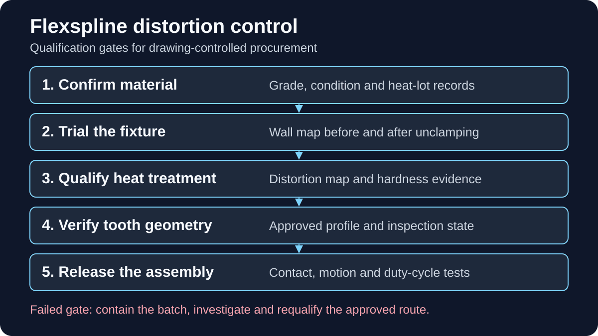
5. Visual: Five Flexspline Qualification Gates
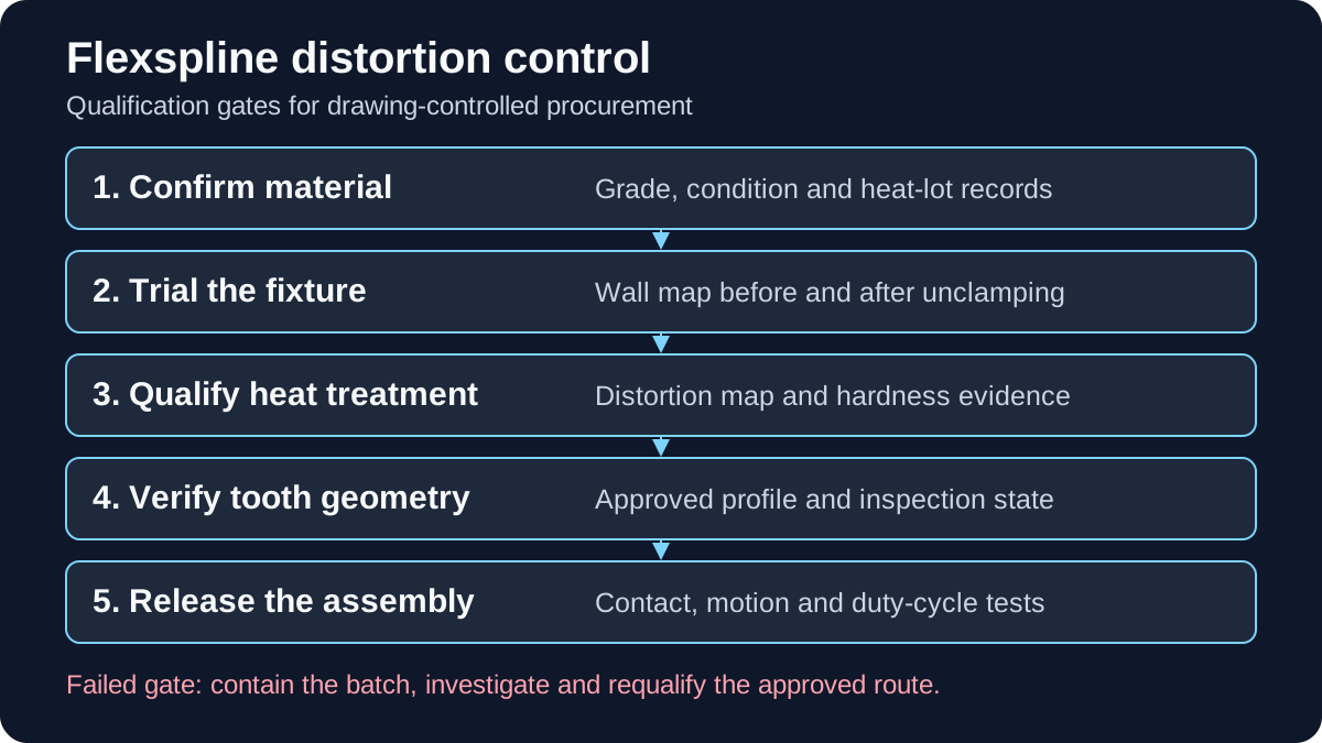
Original procurement workflow illustration, not a component photograph or production-test result. The thermal and tooth-cutting order must follow the qualified route.
Read the gates in sequence: confirm material → trial the fixture → qualify heat treatment → verify final tooth geometry → validate the assembly. A failed gate calls for batch containment, root-cause review, an approved process change, and renewed qualification. Adjusting a CNC offset alone cannot resolve a material or fatigue failure.
6. Surface Integrity: Shot Peening and Residual Stress
Inspect tooth roots, diaphragm transitions, and other highly stressed surfaces for tool marks, burrs, cracks, and process-induced surface changes. Dimensional conformity alone does not establish surface integrity.
Where the design authority specifies shot peening, agree the applicable revision of SAE AMS2430. The linked U revision covers shot peening of part surfaces; its scope does not establish a universal flexspline residual-stress value or a qualified process for the reader’s geometry.
- Coverage and masking: identify treated areas and protected functional surfaces on the drawing or process specification.
- Media and intensity: approve media, intensity, strip type, units, and coverage criteria together. Almen A and N readings are different scales, not interchangeable values.
- Distortion and finish: inspect wall geometry, tooth profile, and surface finish after treatment. A fatigue-improvement process can still move a thin wall outside its dimensional envelope.
- Verification plan: if X-ray diffraction or destructive sections are required, define the method, locations, depth, sample frequency, and acceptance criteria. A companion coupon does not automatically represent residual stress at a curved tooth root.
7. Quality Assurance and Metrology Gate Matrix
Choose contact force and support so inspection does not appreciably deform the cup. Optical methods, low-force probes, air gauges, and dedicated fixtures each have access and uncertainty limits. An LVDT by itself is not necessarily a non-contact measurement system.
Flexspline Quality Assurance Gate Matrix
| Inspection gate | Method and setup to agree | Acceptance evidence |
|---|---|---|
| Incoming material | Heat-lot identity and specified inclusion sampling | Mill certificate plus the agreed test report and purchasing limits |
| Cup wall and roundness | Thickness map and roundness measurement in defined free/restrained states | Drawing limits, axial/angular locations, temperature, and fixture details |
| Tooth geometry | Profile-appropriate gear measurement or validated optical comparison | Approved tooth definition and agreed pitch/profile/lead deviations |
| Tooth modification | Flank map referenced to the specified datum and inspection state | Designer-approved crowning or relief; no generic micron target |
| Diaphragm transition | Accessible optical/profile measurement and surface inspection | Specified radius/blend and allowed surface discontinuities |
| Hardness and microstructure | Grade- and section-appropriate method; destructive sample if needed | Approved material condition; do not indent a thin wall on an unsuitable scale |
| Thermal stability | Agreed dimensional checks and phase analysis where relevant | Drawing/process-specific limits and sampling; no universal retained-austenite threshold |
| Final surface integrity | Defined crack detection, finish, and residual-stress tests where specified | Results after the last surface process with location and method traceability |
| Reducer assembly | Contact/motion checks and duty-cycle testing with mating components | Agreed transmission error, lost motion, torque, temperature, and endurance criteria |
Measurement decision: agree uncertainty and a conformance decision rule before accepting results near a tolerance limit. Repeatability alone is not an uncertainty budget. Keep dimensional acceptance and assembly-life qualification as separate release decisions.
8. The 10-Point Procurement and Drawing Release Checklist
Use this checklist to expose missing inputs before suppliers commit to tooling or delivery dates:
- 1. Exact material: specify grade, governing specification/revision, supply condition, and any approved substitutions.
- 2. Cleanliness and melt route: agree the required route, inclusion-rating method, sampling, and purchaser-defined limits; attach the heat-lot evidence requirement.
- 3. Wall definition: dimension wall and diaphragm thickness, allowable variation, and the positions used for inspection.
- 4. Inspection state: define free or restrained acceptance, datum scheme, fixture contact, clamping condition, temperature, and decision rule.
- 5. Tooth design: supply the approved profile, modifications, transition radii, and mating-part definition; resolve proprietary-profile access before cutting tools are ordered.
- 6. Accuracy criteria: name the applicable standard and revision where suitable, plus the individual deviations and design-specific criteria. Do not assume ISO and AGMA grades are interchangeable.
- 7. Thermal route: approve grade-compatible processing, support, trial quantities, distortion checkpoints, and available finishing stock.
- 8. Stability checks: define whether retained-austenite testing, sub-zero treatment, or dimensional aging checks are needed and how they will be accepted.
- 9. Surface integrity: specify finish, burr/crack limits, and any peening or coating process with its masking, verification, and post-process inspection requirements.
- 10. Traceability and release: identify marking restrictions, heat/batch linkage, first-article report contents, assembly validation, and approval responsibility for process changes.
9. Commercial Sourcing Dynamics and RFQ Template
Compare cost per accepted part, with tooling, qualification, recurring inspection, outside processing, and rejects allocated consistently. Ask whether a quote covers only the machined blank, the finished flexspline, or a validated reducer assembly. Those are different deliverables.
Request separate tooling/NRE, trial, and production prices. Identify outsourced gear cutting, heat treatment, peening, and testing; agree who owns nonconformance resolution. Do not assume any published scrap rate applies to a bidder without its own comparable records.
RFQ Input Data Fields Template
Copy this CSV and replace every bracketed field before requesting a binding quote. It deliberately contains no default production tolerance, alloy equivalence, thermal recipe, or fatigue rating.
field,parameter_value,procurement_engineering_note
project_code,[project and drawing revision],Revision-controlled identifier
part_description,[cup-type or hat-type flexspline],Define blank vs finished component scope
raw_material,[exact grade and delivery condition],Attach governing material specification
material_traceability,[heat lot and test requirements],State melt route and inclusion criteria if required
cup_geometry,[drawing reference and wall map],Define ID OD wall and diaphragm requirements
tooth_definition,[approved profile file and revision],Include modifications and mating-part definition
inspection_state,[free or restrained setup],Define datums fixture conditions and decision rule
thermal_route,[supplier proposal for approval],Include distortion checkpoints and finishing stock
material_condition,[approved property requirements],Define hardness method and microstructure checks
surface_processes,[specified processes or none],Include masking and final inspection
first_article_report,[agreed report contents],Specify sampling and any contract-required FAI standard
assembly_validation,[duty cycle and acceptance plan],Separate component inspection from reducer testing
lot_volume,[trial and annual quantities],Itemize NRE and recurring costs
process_change_control,[approval owner and triggers],Requalify affected characteristics after changes
Frequently Asked Questions (FAQ)
Can we cut flexspline teeth before heat treatment to save tooling costs?
Yes, if the qualified route accommodates subsequent distortion and achieves the final drawing requirements. Compare inspection before and after heat treatment and any corrective finishing. Hard finishing may be appropriate, but it is not automatically feasible or necessary for every tooth form and material condition.
Why does wire EDM need special review for production flexsplines?
Its low mechanical cutting force can help with compliant parts, but surface alteration, tool access, profile requirements, and fatigue duty still require review. If the route leaves a recast layer or requires removal, qualify the final surface and geometry after that operation. Neither automatic rejection nor automatic fatigue approval follows from the process name.
How does wall thickness variation affect harmonic reducer accuracy?
It changes local compliance and can change deformation and contact under the wave generator. The thickness-cubed example above illustrates sensitivity, but it cannot calculate reducer backlash, lost motion, or transmission error. Measure those separately in the specified assembly and operating conditions.
What is the difference between cup-type and hat-type flexsplines?
Their sleeve, diaphragm, and mounting-flange arrangements differ, changing axial packaging, support, load paths, and inspection access. Compare the actual designs and mating interfaces. The shape label alone does not establish superior stiffness, fatigue life, or a tighter fillet tolerance.
Can titanium replace alloy steel in a flexspline?
Treat this as a design change rather than a material substitution. Elastic response, contact wear, lubrication/coating compatibility, manufacturability, and fatigue behavior all require validation with the mating components. This guide provides no qualified titanium route or transferable steel life rating.
Sources and Technical References
Source records checked for this review on 29 October 2026. Standards references identify their scope; use the contractually agreed editions and full texts for production requirements.
- Harmonic Drive — Strain Wave Gear Principle. Manufacturer explanation of the wave generator, compliant flexspline, circular spline, and tooth engagement. Supports the mechanism description, not another supplier’s machining capability or component life rating.
- ASTM International — E45: Standard Test Methods for Determining the Inclusion Content of Steel. Official scope and significance of inclusion-rating methods for wrought steel. It explicitly does not establish universal acceptance limits for a steel grade.
- SAE International — AMS2430U: Shot Peening. Official record for the April 2018 U revision, covering shot peening of part surfaces with metallic, glass, or ceramic media. Confirm the specified edition before procurement; this citation is not a claim that U is the latest revision.
Discuss Your Flexspline Drawing with Linkup Precision
Prepare your STEP model, revision-controlled 2D drawing, approved tooth definition, quantity, and target duty cycle. Linkup Precision can review the machining and sourcing scope, identify specialist-process questions, and agree the evidence needed before a production commitment. Gear cutting, thermal processing, surface treatment, and endurance validation require project-specific capability confirmation.
Author

Categories
More Posts
CNC vs MIM for Robotics Actuators - Cost and Validation Framework
Practical decision framework for actuator teams comparing CNC-first and MIM-transition routes across volume bands, tolerance risk, and pilot release gates.
2026-W21 Industrial Buyer Update: Tariff Coding, Magnetic Supply, and AI Liquid-Cooling Procurement Signals
Decision-focused update for U.S./EU/APAC buyers on tariff coding, magnetic supply continuity, and AI liquid-cooling CNC procurement risk in the last 30 days.
Two-Phase D2C Cold Plate CNC DFM Playbook for AI Rack Programs
A practical DFM and validation checklist for two-phase D2C cold plate machining, from micro-channel geometry to leak-test acceptance criteria.